Steel pipe bend is a bending pipe that used to change the pipeline direction. Common use radius bend in 3D bend and 5D bend, It is similar to pipe elbow, but differently pipe bend is longer than elbow and usually manufactured for the specific needs.
So depends on different bending radius (R) to distinguish bend and elbow.
In case bending radius is more than 2 times of D (diameter), it is pipe bend. Like 3D bend, 5D bend, 6D pipe bend, 8D pipe bend.
In case bending radius in 1D or 1.5D, it is elbow. (short radius elbow 1D and long radius elbow 1.5D).
Pipe Bending Radius: 3D Bend, 5D Bend, 6D, 8D and customized
Bending Degrees: 15°, 22.5°, 30°, 45°, 60°, 90°, 180° and customized
Common Use Bends in Pipelines
3D and 5D bends are most common use in long pipelines, since they provide better efficiency in changing directions. After that is 6D and 8D bend, as the compensation to complete for small degree change.
3D Bend
3D bend radius in 3D, means the bend radius is 3 times of pipe outside diameter. For example if a 3D bend used in a 10 inch pipelines, the bend radius would be 30 inches.
5D Bend
5D bend means the bend radius is 5 times of pipe nominal diameter. It provides better smooth performance to change pipeline direction than 3D bend.
6D Bend
6D bend as one of long radius bend, bend radius “R” is 6 times of pipe diameter, in case of the same degree, it has longer length than 3D or 5D bend, but shorter length than 8D bend.
The radius become bigger, the length of the pipe bend become bigger.
8D Bend
8D bend normally is the longest radius for the common use.
How does steel pipe bend made?
The pipe bend is bent by a set of bending equipment with two processes: Cold simmering and hot pushing. (Including bending, squeezing, pressing, forging, machining and etc)
Pipe Bending Machine by Hot Push Manufacturing
Insert the straight pipe into pipe bending machine, heat the pipe and use lever (installed with different dimension of mould) to bend the pipe.
Differences between Steel Pipe Bend VS Elbow
Pipe bend and elbow both for change the pipe direction, still there are a lot of differences in below aspects:
Bending Radius
Manufacturing Processes
Different cost
Application scope
Bending Radius of Bend 3D, 5D, 8D and Elbow 1D, 1.5D
As we talked above,
Steel pipe bend radius: Above 2 times of D, so there are 2D, 2.5D, 3D, 5D, 6D, 7D or 8D pipe bend.
Steel pipe elbow radius: R=1D or R=1.5D or 2D. Below 1.5D is short radius elbow, and more than 1.5D but not over 2D is long radius elbow.
R is radius of curvature; D is (elbow or bend) pipe diameter.
Large Diameter Pipe Bend / Bending
Steel pipe bending usually required in large diameter in oil and gas pipelines, since it has better capacity to transport the material, and long pipelines will need different radius of pipe bends to be intalled in complex conditions.
Different of manufacturing processes
3D, 5D, 8D Bend: Could be bend directly from a finished pipe with cold bending processes, to different degrees.
1D, 1.5 D Elbow: Shall be made according by standard manufacture procedures, with hot finishing or hot bending, to a certain degree, 45°, 90° or 180°.
Cost different with elbow and 3D, 5D, 6D, 8D bend
So by the help of simple production process with standard 1.5D or 1D, steel pipe elbow cost is lower than bend. Pipe bend is mostly required with customized radius like 3D, 4D, 5D, 6D, 8D or degrees so the processes is more complicated than elbow and cost is higher.
Different applications scope
Bend: Compatible with slower liquid and lower pressure.
Elbow: Compatible with high pressure and rapid liquid.
Sometimes elbows must be used in narrow sections, because the radius of curvature of the elbow is small, generally 1.5D, but the pipe bend could be up to 40D.
So what are 3D bends and what are they for?
A 3D bend is a bend in which the radius of the curve is equal to 3 times the diameter of the pipe. It is a smoother bend than a 1.5D bend, which looks almost like a regular 90-degree right angle, but it is a sharper bend than a 5D bend, which looks like a smooth arc between two perpendicular pieces.
Here are a few of the places where you will commonly find 3D bends being used:
1. Automotive Exhaust Systems
Both manufacturer-supplied and custom exhaust systems for cars and trucks often feature a wide assortment of bends to maneuver around various obstacles on the underside of the car, such as the engine, transmission, cross-members and the fame. Most vehicle exhausts feature custom compound beds, and the fabricators generally prefer smoother curves, like 3D bends or even 5D bends, because they reduce the turbulence and back-pressure inside the exhaust system, and that can help increase an engine’s performance.
2. Automotive Roll Cages
Off-roading can be a very competitive sport, or, more simply, an expensive hobby. One of the many dangers when rock-crawling, mudding or generally pushing a vehicle beyond its limits, is the possibility of rolling the vehicle over. To prevent injury and damage to the vehicle, a quality roll cage is an absolute necessity. Many roll cages are custom formed from metal pipe, often chromoly steel, using an assortment of bends, including the common 3D bend. Each piece is bent, cut and welded together to make a complete roll cage that is both durable and aesthetically pleasing.
3. Structural Frames
3D bends are very common in structural frames of all kinds. These can range from the frames of custom automobiles, to the frames of buildings, or even airplanes or spacecraft. Often, to build a structural frame, pipe is bent, cut and welded together to make a strong skeleton, and then sheet metal is attached via screws or welds to create a completed assembly, which is both extremely strong and resistant to the elements. When built using aluminum, titanium or certain alloys, it can also be lightweight and corrosion-resistant.
4. Furniture
Many types of furniture incorporate tubular steel and 3D bends for either structural or aesthetic purposes. Tables frequently use tubular steel legs, with bends where they meet the tabletop to provide support. Metal chairs, couches and futons with tubular frames often use similar bends to provide a nice gentle curve that is both pleasing to the eye and structurally rigid. Shelving units can also incorporate custom bends, either for decoration or for structural integrity.
5. Fencing
The 3D bend is also quite common in fencing, for both decorative and structural uses. It is seen extensively in galvanized chain-link fencing, especially to add a gentle curve to gates and other decorative items, or in custom-designed fencing. Pipe is also used regularly in fencing for cattle, horses and other livestock, as well as for domestic pets, and often decorative touches are added that require custom bends.
6. Plumbing
In the plumbing industry, 3D bends are quite common. They are incorporated anywhere that standard elbows cannot be relied upon to bypass obstacles or to change the angle of the pipe. In pipes that contain high-viscosity liquids or fluids that require reduced turbulence, the smoother 3D bend is often preferable to sharper bends. Custom bends are used in plumbing of all kinds, from the pipes in your home, to the pipes in chemical plants, food processors or refineries.
7. Wiring Conduit
Wiring conduit is designed to protect electrical cables from the weather, accidental damage and other dangers. When wiring conduit is required on an electrical job, often it must be bent to go around corners or other obstacles. Typically, smoother curves like 3D or 5D bends are used instead of sharp curves, because it makes it much easier to fish the wire through the conduit after it is installed. Electricians usually carry their own tools to bend small-diameter conduit, though for larger-diameter versions, they may require custom bending services.
8. Pipelines
Gas and oil pipelines, like any plumbing system, often use 3D bends in many places along their lengths. Unlike typical household pipes, however, these are typically much larger, and require some serious machinery to do custom bends. Gentle bends help the high-viscosity oil flow through the pipes easier, and they help natural gas flow smoother, reducing pipe fatigue and the chance of leaks.
9. Hand Rails
An often-overlooked area where 3D bends are used is in the hand rails for stairways or walkways, as well as the safety rails used to provide handicap access. Custom bends are often used to follow curves, go around corners or to provide mounting points at each end of the pipe. Sometimes the bends are also used strictly for decorative purposes.
10. Art Projects
In many art projects, tubular steel is used to create a frame, upon which the artist builds the rest of the piece. Custom bends are often used to create gentle-flowing lines and other aesthetic features, which many times are covered up by other materials. The frame creates a strong base for the rest of the piece, and determines its overall shape.
If you have a project that calls for 3D bends, it often may not be feasible to buy the equipment to produce them yourself. The tools can be prohibitively expensive, and they require a significant amount of training and practice to operate them properly. Fortunately, there are services available that will custom-bend pipe to your exact specifications, saving you the expense and the hassle of buying your own equipment.
Methods of bends in carbon steel
While the industry provides various means for bending the carbon steel pipe to the 5D bend, heat induction is the most widely-known–but not the most popular–technique in the industry. The pipe to be bent is subjected to extreme temperature, and when at the desired heat, a mode or model in the dimensions of the 5D bends is forced through the heated pipe, causing the pipe to conform to the bend of the 5D pipe dimensions. Carbon steel is the hardest pipe material used in this manner, and heat induction is the best means to curve the carbon steel pipe into the 5D curvature.
Uses
Heat-processed 5D bend pipes are used in all oil and gas lines, and the factory testing exceeds the quality standards required by the oil and gas industry. This is an industry where quality standards can be linked to safety standards.
What You Are Buying
Customers obtain a wide range of bend geometries and total design flexibility with customized radius and angle. Qualified subcontractors carry out hot induction bending with state-of-the-art technology, giving full control of the bending process, as well as total monitoring of all bending parameters.
1) Heat Induction Bends for Oil and Gas Industry
The production of high-quality bends depends on the manufacturing process of the steel pipe that is transformed into the bend. During the hot-induction bending process, unavoidable thinning occurs. Therefore, a custom- and precision-made mother pipe must be produced in order to comply with minimum wall thickness after the bending is complete.
Heat treatment is carried out on each bend in order to achieve the required degree and mechanical properties after bending. For critical applications (such as high-strength steel, heavy wall, sour service or low-temperature) full quenching and tempering after bending is still performed as a preferred process. Machining the bend ends guarantees top tolerances of inside diameters of the pipe. We therefore ensure the bend has the minimum working strengths of the mother pipe.
World-class bending manufacturers provide high quality bending solutions for oil and gas pipelines, either onshore or offshore. The bends manufacturing and testing procedures exceed all quality standards required by the oil and gas industry.
2) Cold Bending Process
High quality bending solutions are more than critical. Cold-bending is commonly used over hot-bending because certain types of steel and metal alloys can be weakened. You cannot allow the pipes to be weakened in any way as this can lead to damage of your product, your plant, or cause risks of injury to your employees. Cold-bending is also preferred by many industries because of its affordability, with costs being less than that of heat induction.
Cold-bending 5D bends is a continuous operation where a long strip of metal, usually steel, is passed through sets of rollers, with each set of rollers performing only a part of the bend, until the desired cross-section profile is obtained. Roll-forming is ideal for producing parts with long lengths or in large quantities. Roll-Forming is also generally a lower cost process than other metal forming processes. Cold-processed bends are used in construction, water piping and as machinery parts.
Sunny Steel provides fast, dependable metal custom-bending for:
angle
flat bar
round tube
pipe
square tube
Ibeams
channel
finned tube
We specialize in bending, fabricating and testing of heating and cooling coils. We are proud of our leading reputation in the industry with our attitude of professional workmanship and on-time delivery. Some of our advantages over competitors include:
Fast Turnaround Times
Dependability
Outstanding Reputation
Custom Pipe Bending
Custom Oil Field Bending
Architectural Application Bending
Heating and Cooling Coil Fabrication
Sunny Steel fabricates all types and sizes of cooling coils from 1/8″ pipe to 8″ pipe and all alloys.
Size
The bend is used to change the direction of run of pipe.it advantage is can matach long distance transition requirements,so it is commonly that bends dimension according to customer design.
Constants for Pipe Bends:
Formula:L = R x BL = Length of pipe requiredR = Radius of bendB = Constant from table used to find “L”L =30 x 1.5705 =47.115 in.or 47-1/8”
Outer diamete(D): D≤1800mm
Wall thickness(T): T≤120mm
Straight Length (L): The length between two ends general from 300mm-1500mm
Example: Find the length of pipe required to make a 90 bend with a radius of 30"
Nominal pipe
Outside Diameter at Bevel
Center to End
DN size
D1
D2
C
M
Series A
Series B
Series A
Series B
20×15
26.9
25
21.3
18
29
29
25×20
33.7
32
26.9
25
38
38
25×15
33.7
32
21.3
18
38
38
32×25
42.4
38
33.7
32
48
48
32×20
42.4
38
26.9
25
48
48
32×15
42.4
38
21.3
18
48
48
40×32
48.3
45
42.4
38
57
57
40×25
48.3
45
33.7
32
57
57
40×20
48.3
45
26.7
25
57
57
40×15
48.3
45
21.3
18
57
57
50×40
60.3
57
48.3
45
64
60
50×32
60.3
57
42.4
38
64
57
50×25
60.3
57
33.7
32
64
51
50×20
60.3
57
26.9
25
64
44
65×50
76.1(73)
76
60.3
57
76
70
65×40
76.1(73)
76
48.3
45
76
67
65×32
76.1(73)
76
42.4
38
76
64
65×25
76.1(73)
76
33.7
32
76
57
80×65
88.9
89
76.1(73)
76
86
83
80×50
88.9
89
60.3
57
86
76
80×40
88.9
89
48.3
45
86
73
80×32
88.9
89
42.4
38
86
70
90×80
101.6
-
88.9
-
95
92
90×65
101.6
-
76.1(73)
-
95
89
90×50
101.6
-
60.3
-
95
83
90×40
101.6
-
48.3
-
95
79
100×90
114.3
-
101.6
-
105
102
100×80
114.3
108
88.9
89
105
98
100×65
114.3
108
76.1(73)
76
105
95
100×50
114.3
108
60.3
57
105
89
100×40
114.3
108
48.3
45
105
86
125×100
139.7
133
114.3
108
124
117
125×90
139.7
-
101.6
-
124
114
125×80
139.7
133
88.9
89
124
111
125×65
139.7
133
76.1(73)
76
124
108
125×50
133
60.3
57
124
105
150×125
168.3
159
139.7
133
143
137
150×100
168.3
159
114.3
108
143
130
150×90
168.3
-
101.6
-
143
127
150×80
168.3
159
88.9
89
143
124
150×65
168.3
159
76.1(73)
76
143
121
200×150
219.1
219
168.3
159
178
168
200×125
219.1
219
139.7
133
178
162
200×100
219.1
219
114.3
108
178
156
200×90
219.1
-
101.6
-
178
152
200×200
273
273
219.1
219
216
208
200×150
273
273
168.3
159
216
194
200×125
273
273
139.7
133
216
191
200×100
273
273
114.3
108
216
184
300×250
323.9
325
273
273
254
241
300×200
323.9
325
219.1
219
254
229
300×150
323.9
325
168.3
159
254
219
300×125
323.9
325
139.7
133
254
216
350×300
355.6
377
323.9
325
279
270
350×250
355.6
377
273
273
279
257
350×200
355.6
377
219.1
219
279
248
350×150
355.6
377
168.3
159
279
238
400×350
406.4
426
355.6
377
305
305
400×300
406.4
426
323.9
325
305
295
400×250
406.4
426
273
273
305
283
400×200
406.4
426
219.1
219
305
273
400×150
406.4
426
168.3
159
305
264
450×400
457.2
478
406.4
426
343
330
450×350
457.2
478
355.6
377
343
330
450×300
457.2
478
323.9
325
343
321
450×250
457.2
478
273
273
343
308
450×200
457.2
478
219.1
219
343
298
500×450
508
529
457.2
478
381
368
500×100
508
529
406.4
426
381
356
500×350
508
529
355.6
377
381
356
500×300
508
529
323.9
325
381
346
500×250
508
529
273
273
381
333
500×200
508
529
219.1
219
381
324
550×500
559
-
508
-
419
406
550×450
559
-
457
-
419
394
550×400
559
-
406
-
419
381
600×550
610
-
559
-
432
432
600×550
610
630
508
530
432
432
600×450
610
630
457
480
432
419
650×600
660
-
610
-
495
483
650×550
660
-
559
-
495
470
650×500
660
-
508
-
495
457
700×650
711
-
660
-
521
521
700×600
711
720
610
630
521
508
700×550
711
-
559
-
521
495
750×700
762
-
711
-
559
546
750×650
762
-
660
-
559
546
750×600
762
-
610
-
559
533
800×750
813
-
762
-
597
584
800×700
813
820
711
720
597
572
800×650
813
-
660
-
597
572
850×800
864
-
813
-
635
622
850×750
864
-
762
-
635
610
850×700
864
-
711
-
635
597
900×850
914
-
864
-
673
660
900×800
914
920
813
820
673
648
900×750
914
-
762
-
673
635
950×900
965
-
914
-
711
711
950×850
965
-
864
-
711
698
950×800
965
-
813
-
711
686
1000×950
1016
-
965
-
749
749
1000×900
1016
1020
914
920
749
737
1000×8500
1016
-
864
-
749
724
1000×1000
1067
-
1016
-
762
711
1050×950
1067
-
965
-
762
711
1050×900
1067
-
914
-
762
711
1100×1050
1118
-
1067
-
813
762
1100×1000
1118
1120
1016
1020
813
749
1100×950
1118
-
965
-
813
737
1150×1100
1168
-
1118
-
851
800
1150×1050
1168
-
1067
-
851
787
1150×1000
1168
-
1016
-
851
775
1200×1150
1220
-
1168
-
889
838
1200×1100
1220
1220
1118
1120
889
838
1200×1050
1220
-
1067
-
889
813
Beveling
In the behavior, we make beveling after shot blasting, bevel ends are fully machined by advanced equipment Double Beveling Machine ensure the height, length, thickness, O.D. and I.D. are all qualified.
ASME B16.28, Buttwelding Short Radius Elbows and Returns
ANSI/ASME B16.25, Buttwelding Ends
MSS SP-97, Socket Welding, Threaded, and Buttwelding Ends
The ends of all buttweld fittings are bevelled, exceeding wall thickness 4 mm for austenitic stainless steel, or 5 mm for ferritic stainless steel. The shape of the bevel depending upon the actual wall thickness. This bevelled ends are needed to be able to make a “Butt weld”.
ASME B16.25 covers the preparation of buttwelding ends of piping components to be joined into a piping system by welding. It includes requirements for welding bevels, for external and internal shaping of heavy-wall components, and for preparation of internal ends (including dimensions and dimensional tolerances).
Our in-hourse R&D team developed bevel ends equipment are good using in thickness 2mm to 20mm pipe fittings, guarantee high efficiency and high quality.
These weld edge preparation requirements are also incorporated into the ASME standards (e.g., B16.9, B16.5, B16.34).
Nominal wall Thickness : t
End Preparation
t<5mm (for austenitic alloy steel
Cut square or slightly chamfer
t<4mm)
at manufacturer ' s option
5
(4
Plain Bevel as in sketch ( a ) above
t>22mm
Compound Bevel as in sketch ( b ) above
Nominal pipe
Outside Diameter at Bevel
Center to End
DN size
D1
D2
C
M
Series A
Series B
Series A
Series B
20×15
26.9
25
21.3
18
29
29
25×20
33.7
32
26.9
25
38
38
25×15
33.7
32
21.3
18
38
38
32×25
42.4
38
33.7
32
48
48
32×20
42.4
38
26.9
25
48
48
32×15
42.4
38
21.3
18
48
48
40×32
48.3
45
42.4
38
57
57
40×25
48.3
45
33.7
32
57
57
40×20
48.3
45
26.7
25
57
57
40×15
48.3
45
21.3
18
57
57
50×40
60.3
57
48.3
45
64
60
50×32
60.3
57
42.4
38
64
57
50×25
60.3
57
33.7
32
64
51
50×20
60.3
57
26.9
25
64
44
65×50
76.1(73)
76
60.3
57
76
70
65×40
76.1(73)
76
48.3
45
76
67
65×32
76.1(73)
76
42.4
38
76
64
65×25
76.1(73)
76
33.7
32
76
57
80×65
88.9
89
76.1(73)
76
86
83
80×50
88.9
89
60.3
57
86
76
80×40
88.9
89
48.3
45
86
73
80×32
88.9
89
42.4
38
86
70
90×80
101.6
-
88.9
-
95
92
90×65
101.6
-
76.1(73)
-
95
89
90×50
101.6
-
60.3
-
95
83
90×40
101.6
-
48.3
-
95
79
100×90
114.3
-
101.6
-
105
102
100×80
114.3
108
88.9
89
105
98
100×65
114.3
108
76.1(73)
76
105
95
100×50
114.3
108
60.3
57
105
89
100×40
114.3
108
48.3
45
105
86
125×100
139.7
133
114.3
108
124
117
125×90
139.7
-
101.6
-
124
114
125×80
139.7
133
88.9
89
124
111
125×65
139.7
133
76.1(73)
76
124
108
125×50
133
60.3
57
124
105
150×125
168.3
159
139.7
133
143
137
150×100
168.3
159
114.3
108
143
130
150×90
168.3
-
101.6
-
143
127
150×80
168.3
159
88.9
89
143
124
150×65
168.3
159
76.1(73)
76
143
121
200×150
219.1
219
168.3
159
178
168
200×125
219.1
219
139.7
133
178
162
200×100
219.1
219
114.3
108
178
156
200×90
219.1
-
101.6
-
178
152
200×200
273
273
219.1
219
216
208
200×150
273
273
168.3
159
216
194
200×125
273
273
139.7
133
216
191
200×100
273
273
114.3
108
216
184
300×250
323.9
325
273
273
254
241
300×200
323.9
325
219.1
219
254
229
300×150
323.9
325
168.3
159
254
219
300×125
323.9
325
139.7
133
254
216
350×300
355.6
377
323.9
325
279
270
350×250
355.6
377
273
273
279
257
350×200
355.6
377
219.1
219
279
248
350×150
355.6
377
168.3
159
279
238
400×350
406.4
426
355.6
377
305
305
400×300
406.4
426
323.9
325
305
295
400×250
406.4
426
273
273
305
283
400×200
406.4
426
219.1
219
305
273
400×150
406.4
426
168.3
159
305
264
450×400
457.2
478
406.4
426
343
330
450×350
457.2
478
355.6
377
343
330
450×300
457.2
478
323.9
325
343
321
450×250
457.2
478
273
273
343
308
450×200
457.2
478
219.1
219
343
298
500×450
508
529
457.2
478
381
368
500×100
508
529
406.4
426
381
356
500×350
508
529
355.6
377
381
356
500×300
508
529
323.9
325
381
346
500×250
508
529
273
273
381
333
500×200
508
529
219.1
219
381
324
550×500
559
-
508
-
419
406
550×450
559
-
457
-
419
394
550×400
559
-
406
-
419
381
600×550
610
-
559
-
432
432
600×550
610
630
508
530
432
432
600×450
610
630
457
480
432
419
650×600
660
-
610
-
495
483
650×550
660
-
559
-
495
470
650×500
660
-
508
-
495
457
700×650
711
-
660
-
521
521
700×600
711
720
610
630
521
508
700×550
711
-
559
-
521
495
750×700
762
-
711
-
559
546
750×650
762
-
660
-
559
546
750×600
762
-
610
-
559
533
800×750
813
-
762
-
597
584
800×700
813
820
711
720
597
572
800×650
813
-
660
-
597
572
850×800
864
-
813
-
635
622
850×750
864
-
762
-
635
610
850×700
864
-
711
-
635
597
900×850
914
-
864
-
673
660
900×800
914
920
813
820
673
648
900×750
914
-
762
-
673
635
950×900
965
-
914
-
711
711
950×850
965
-
864
-
711
698
950×800
965
-
813
-
711
686
1000×950
1016
-
965
-
749
749
1000×900
1016
1020
914
920
749
737
1000×8500
1016
-
864
-
749
724
1000×1000
1067
-
1016
-
762
711
1050×950
1067
-
965
-
762
711
1050×900
1067
-
914
-
762
711
1100×1050
1118
-
1067
-
813
762
1100×1000
1118
1120
1016
1020
813
749
1100×950
1118
-
965
-
813
737
1150×1100
1168
-
1118
-
851
800
1150×1050
1168
-
1067
-
851
787
1150×1000
1168
-
1016
-
851
775
1200×1150
1220
-
1168
-
889
838
1200×1100
1220
1220
1118
1120
889
838
1200×1050
1220
-
1067
-
889
813
Nominal pipe size
Outside Diameter at Bevel
Center to End
D
C
M
DN
INCH
Series A
Series B
15
1/2
21.3
18
25
20
3/4
26.9
25
29
25
1
33.7
32
38
32
1 1/4
42.4
38
48
40
1 1/2
48.3
45
57
50
2
60.3
57
64
65
2 1/2
76.1(73)
76
76
80
3
88.9
89
86
90
3 1/2
101.6
―
95
100
4
114.3
108
105
125
5
139.7
133
124
150
6
168.3
159
143
200
8
219.1
219
178
250
10
273
273
216
300
12
323.9
325
254
350
14
355.6
377
279
400
16
406.4
426
305
450
18
457.2
478
343
500
20
508
529
381
550
22
559
―
419
600
24
610
630
432
650
26
660
―
495
700
28
711
720
521
750
30
762
―
559
800
32
813
820
597
850
34
864
―
635
900
36
914
920
673
950
38
965
―
711
1000
40
1016
1020
749
1050
42
1067
―
762
711
1100
44
1118
1120
813
762
1150
46
1168
―
851
800
1200
48
1220
1220
889
838
Standard
Pipe fitting dimensions are in either metric or Standard English. Because pipe fitting covers Pipe Fitting Dimensions several aspects, only the most common pipe fitting sizes can be given here. The most applied version is the 90° long radius and the 45° elbow, while the 90° short radius elbow is applied if there is too little space. The function of a 180° elbow is to change direction of flow through 180°. Both, the LR and the SR types have a center to center dimension double the matching 90° elbows. These fittings will generally be used in furnesses or other heating or cooling units.
Some of the standards that apply to buttwelded fittings are listed below. Many organizations such as ASME, ASTM, ISO, MSS, etc. have very well developed standards and specifications for buttwelded fittings. It is always up to the designer to ensure that they are following the applicable standard and company specification, if available, during the design process.
Some widely used pipe fitting standards are as follows:
ASME: American Society for Mechanical Engineers
This is one of the reputed organizations in the world developing codes and standards.
The schedule number for pipe fitting starts from ASME/ANSI B16. The various classifications of ASME/ANSI B16 standards for different pipe fittings are as follows:
ASME/ANSI B16.1 – 1998 – Cast Iron Pipe Flanges and Flanged Fittings
ASME/ANSI B16.3 – 1998 – Malleable Iron Threaded Fittings
ASME/ANSI B16.4 – 1998 – Cast Iron Threaded Fittings
ASME/ANSI B16.5 – 1996 – Pipe Flanges and Flanged Fittings
ASTM International: American Society for Testing and Materials
This is one of the largest voluntary standards development organizations in the world. It was originally known as the American Society for Testing and Materials (ASTM).
ASTM A105 / A105M – Specification for Carbon Steel Forgings for Piping Applications
ASTM A234 / A234M – Specification for Piping Fittings of Wrought Carbon Steel and Alloy Steel for Moderate and High Temperature Service
ASTM A420 / A420M – Standard Specification for Piping Fittings of Wrought Carbon Steel and Alloy Steel for Low-Temperature Service
AWWA: American Water Works Association
AWWA About – Established in 1881, the American Water Works Association is the largest nonprofit, scientific and educational association dedicated to managing and treating water, the world’s most important resource.
AWWA C110 – Ductile-Iron and Gray-Iron Fittings, 3 Inch Through 48 Inch (75 mm Through 1200 mm), for Water and Other Liquids
AWWA C208 – Dimensions for Fabricated Steel Water Pipe Fittings
ANSI: The American National Standards Institute
ANSI is a private, non-profit organization. Its main function is to administer and coordinate the U.S. voluntary standardization and conformity assessment system. It provides a forum for development of American national standards. ANSI assigns “schedule numbers”. These numbers classify wall thicknesses for different pressure uses.
MSS STANDARDS: Manufacturers Standardization Society
The Manufacturers Standardization Society (MSS) of the Valve and Fittings Industry is a non-profit technical association organized for development and improvement of industry, national and international codes and standards for: Valves, Valve Actuators, Valve Modification, Pipe Fittings, Pipe Hangers, Pipe Supports, Flanges and Associated Seals
MSS SP-43 – Wrought Stainless Steel Butt-Welding Fittings Including Reference to Other Corrosion Resistant Materials
MSS SP-75 – Specifications for High Test Wrought Buttwelding Fittings
MSS SP-73 – Brazing Joints for Copper and Copper Alloy Pressure Fittings
MSS SP-83 – Class 3000 Steel Pipe Unions, Socket-Welding and Threaded
MSS SP-106 – Cast Copper Alloy Flanges and Flanged Fittings Class 125,150, and 300
MSS SP-119 – Factory-Made Wrought Belled End Socket Welding Fittings
Difference between “Standard” and “Codes”:
Piping codes imply the requirements of design, fabrication, use of materials, tests and inspection of various pipe and piping system. It has a limited jurisdiction defined by the code. On the other hand, piping standards imply application design and construction rules and requirements for pipe fittings like adapters, flanges, sleeves, elbows, union, tees, valves etc. Like a code, it also has a limited scope defined by the standard.
Factors affecting standards: “Standards” on pipe fittings are based on certain factors like as follows:
Pressure-temperature ratings
Size
Design
Coatings
Materials
Marking
End connections
Dimensions and tolerances
Threading
Pattern taper etc.
BSP: British Standard Pipe
BSP is the U.K. standard for pipe fittings. This refers to a family of standard screw thread types for interconnecting and sealing pipe ends by mating an external (male) with an internal (female) thread. This has been adopted internationally. It is also known as British Standard Pipe Taper threads (BSPT )or British Standard Pipe Parallel (Straight) threads (BSPP ). While the BSPT achieves pressure tight joints by the threads alone, the BSPP requires a sealing ring.
JIS: Japanese Industrial Standards
This is the Japanese industrial standards or the standards used for industrial activities in Japan for pipe, tube and fittings and published through Japanese Standards Associations.
NPT: National Pipe Thread
National Pipe Thread is a U.S. standard straight (NPS) threads or for tapered (NPT) threads. This is the most popular US standard for pipe fittings. NPT fittings are based on the internal diameter (ID) of the pipe fitting.
BOLTS & NUTS
We are manufacturer of Flange bolts & Nuts and supply high quality
A193 = This specification covers alloy and stainless steel bolting material for pressure vessels, Valves, flanges, and fittings for high temperature or high pressure service, or other special purpose applications.
A320 = Standard Specification for Alloy-Steel and Stainless Steel Bolting Materials for Low-Temperature Service.
A194 = Standard specification for nuts in many different material types.
AN: Here, “A” stands for Army and “N” stands for Navy
The AN standard was originally designed for the U.S. Military. Whenever, a pipe fitting is AN fittings, it means that the fittings are measured on the outside diameter of the fittings, that is, in 1/16 inch increments.
For example, an AN 4 fitting means a fitting with an external diameter of approximately 4/16″ or ¼”. It is to be noted that approximation is important because AN external diameter is not a direct fit with an equivalent NPT thread.
Dash (-) size
Dash size is the standard used to refer to the inside diameter of a hose. This indicates the size by a two digit number which represents the relative ID in sixteenths of an inch. This is also used interchangeably with AN fittings. For example, a Dash “8” fitting means an AN 8 fitting.
ISO: International Organization for Standardization
ISO is the industrial pipe, tube and fittings standards and specifications from the International Organization for Standardization. ISO standards are numbered. They have format as follows:
“ISO[/IEC] [IS] nnnnn[:yyyy] Title” where
nnnnn: standard number
yyyy: year published, and
Title: describes the subject
How are pipe fittings measured?
Pipe fittings are measured by their diameter, wall thickness (known as “schedule”), and shape or configuration. (Fittings are also defined by their material grade and whether they are welded or seamless.)
Diameter refers to outside diameter of a pipe or fitting.
The North American standard is known as Nominal Pipe Size (NPS). The International Standard is known as Diameter Nominal (DN). Pipes and fittings are actually made in similar sizes around the world: they are just labeled differently.
From ½ in to 12 inch “Nominal Pipe Size”, outside diameters are slightly larger than indicated size; inside diameters get smaller as schedules grow.
From 14 in and larger “Nominal Pipe Size”, outside diameters are exactly as indicated size; inside diameters get smaller as schedules grow.
As with other North American standards (inch, foot, yard, mile, …), many pipe standards (diameters up to 12 inch and wall thickness) are based on historical precedents (a toolmaker’s dies during US Civil War) rather than a “scientific” method.
Schedule Numbers
The schedule numbers are used by the ANSI (American National Standards Institute) to denote wall thickness. The schedule numbers encompass all pipe dimensions beginning at NPS 1/8” up NPS 36”. Note that this configuration is only for fittings that match with a particular ANSI schedule number.
Nominal Pipe Size (NPS) is a North American set of standard sizes for pipes used for high or low pressures and temperatures.
Schedule, often shortened as sch, is a North American standard that refers to wall thickness of a pipe or pipe fitting. Higher schedules mean thicker walls that can resist higher pressures.
Pipe standards define these wall thicknesses: SCH 5, 5S, 10, 10S, 20, 30, 40, 40S, 60, 80, 80S, 100, 120, 140, 160, STD, XS and XXS. (S following a number is for stainless steel. Sizes without an S are for carbon steel.)
Higher schedules are heavier, require more material and are therefore more costly to make and install.
What does “schedule” mean for pipe fittings?
Schedule, often shortened as SCH, is a North American standard that refers to wall thickness of a pipe or pipe fitting.
What is schedule 40, SCH80?
Higher schedules mean thicker walls that can resist higher pressures.
Pipe standards define these wall thicknesses: SCH 5, 5S, 10, 10S, 20, 30, 40, 40S, 60, 80, 80S, 100, 120, 140, 160, STD, XS and XXS.
(S following a number is for stainless steel. Sizes without an S are for carbon steel.)
Higher schedules are heavier, require more material and are therefore more costly to make and install.
General standard
Standard
Specification
ASTM A234
Standard Specification for Piping Fittings of Wrought Carbon Steel and Alloy Steel for Moderate and High Temperature Service
ASTM A420
Standard Specification for Piping Fittings of Wrought Carbon Steel and Alloy Steel for Low-Temperature Service
ASTM A234 WPB
ASTM A234 is Standard Specification for steel pipe fittings includes carbon and alloy steel material for moderate and high temperature services. WPB is one of the steel grade in this standard
ASME B16.9
ASME B16.9 Standard covers overall dimensions, tolerances,ratings, testing, and markings for factory-made wrought buttwelding fittings in sizes NPS 1⁄2 through NPS 48 (DN 15 through DN 1200).
ASME B16.28
ASME B16.28 Standard covers ratings, overall dimensions, testing, tolerances, and markings for wrought carbon and alloy steel buttwelding short radius elbows and returns.
MSS SP-97
MSS SP-97 Standard Practice covers essential dimensions, finish, tolerances, testing, marking, material, and minimum strength requirements for 90 degree integrally reinforced forged branch outlet fittings of buttwelding, socket welding, and threaded types.
ASTM A403
Standard Specification for Wrought Austenitic Stainless Steel Piping Fittings.
Wide variety for all areas of application
DIN
EN
ASME
St 35.8 I
St 35.8 III
15 Mo 3
13 CrMo 4 4
10 CrMo 9 10
St 35 N
St 52.0
St 52.4
ASTM A234/ASME SA234M standard specification for piping fittings of wrought carbon steel and alloy steel for moderate and high temperature service.
Chemical Composition (%) of ASTM A234/A234M
Grade
Type
C
Si
S
P
Mn
Cr
Ni
Mo
Other
ób
ós
δ5
WPB
0.3
0.1min
0.058
0.05
0.29-1.06
0.4
0.4
0.15
V:0.06;Nb:0.02
415-585
240
22
197
WPC
0.35
0.1min
0.058
0.05
0.29-1.06
0.4
0.4
0.15
V:0.06;Nb:0.02
485-655
275
22
197
WP1
0.28
0.1-0.5
0.045
0.045
0.3-0.9
0.44-0.65
380-550
205
22
197
WP12 CL1
0.05-0.2
0.6
0.045
0.045
0.3-0.8
0.8-1.25
0.44-0.65
415-585
220
22
197
WP12 CL2
0.05-0.2
0.6
0.045
0.045
0.3-0.8
0.8-1.25
0.44-0.65
485-655
275
22
197
WP11 CL1
0.05-0.15
0.5-1
0.03
0.03
0.3-0.6
1-1.5
0.44-0.65
415-585
205
22
197
WP11 CL2
0.05-0.2
0.5-1
0.04
0.04
0.3-0.8
1-1.5
0.44-0.65
485-655
275
22
197
WP11 CL3
0.05-0.2
0.5-1
0.04
0.04
0.3-0.8
1-1.5
0.44-0.65
520-690
310
22
197
WP22 CL1
0.05-0.15
0.5
0.04
0.04
0.3-0.6
1.9-2.6
0.87-1.13
415-585
205
22
197
WP22 CL3
0.05-0.15
0.5
0.04
0.04
0.3-0.6
1.9-2.6
0.87-1.13
520-690
310
22
197
WP5 CL1
0.15
0.5
0.03
0.04
0.3-0.6
4-6
0.44-0.65
415-585
205
22
217
WP5 CL3
0.15
0.5
0.03
0.04
0.3-0.6
4-6
0.44-0.65
520-690
310
22
217
WP9 CL1
0.15
1
0.03
0.03
0.3-0.6
8-10
0.9-1.1
415-585
205
22
217
WP9 CL3
0.15
1
0.03
0.03
0.3-0.6
8-10
0.9-1.1
520-690
310
22
217
WPR
0.2
0.05
0.045
0.4-1.06
1.6-2.24
435-605
315
22/28
217
WP91
0.08-0.12
0.2-0.5
0.01
0.02
0.3-0.6
8-9.5
0.4
0.85-1.05
See sdandard
585-760
415
20
248
WP911
0.09-0.13
0.1-0.5
0.01
0.02
0.3-0.6
8.5-10.5
0.4
0.9-1.1
See sdandard
620-840
440
20
248
Notes:
For each reduction of 0.01% below the specified C maximum, an increase of 0.06% Mn above the specified maximum will be permitted, up to a maximum of 1.35%.
The sum of Cu, Ni, Cr, and Mo shall not exceed 1.00%.
The sum of Cr and Mo shall not exceed 0.32%.
The maximum carbon equivalent (C.E.) shall be 0.50, based on heat analysis and the formula C.E.=C+Mn/6+(Cr+Mo+V)/5+(Ni+Cu)/15.
Mechanical properties of ASTM A234
Tensile Requirements
WPB
WPC, WP11CL2
WP11CL1
WP11CL3
Tensile Strength, min, ksi[MPa]
(0.2% offset or 0.5% extension-under-load)
60-85
[415-585]
70-95
[485-655]
60-85
[415-585]
75-100
[520-690]
Yield Strength, min, ksi[MPa]
32
[240]
40
[275]
30
[205]
45
[310]
ASTM A403
ASTM A403 Standard specification covers the standard for wrought austenitic stainless steel fittings for pressure piping applications.
Chemical Composition (%) of ASTM A403
Steel No.
Type
C
Si
S
P
Mn
Cr
Ni
Mo
Other
ób
ós
δ5
WP304
0.08
1
0.03
0.045
2
18-20
8-11
515
205
28
WP304H
0.04-0.1
1
0.03
0.045
2
18-20
8-11
515
205
28
WP304L
0.035
1
0.03
0.045
2
18-20
8-13
485
170
28
WP304LN
0.03
0.75
0.03
0.045
2
18-20
8-10.5
N2:0.1-0.16
515
205
28
WP304N
0.08
0.75
0.03
0.045
2
18-20
8-11
N2:0.1-0.16
550
240
28
WP309
0.15
1
0.03
0.045
2
22-24
12-15
515
205
28
WP310
0.15
1.5
0.03
0.045
2
24-26
19-22
515
205
28
WP316
0.08
1
0.03
0.045
2
16-18
10-14
2-3
515
205
28
WP316H
0.04-0.1
1
0.03
0.045
2
16-18
10-14
2-3
515
205
28
WP316LN
0.03
0.75
0.03
0.045
2
16-18
11-14
2-3
N2:0.1-0.16
515
205
28
WP316L
0.035
1
0.03
0.045
2
16-18
10-16
2-3
485
170
28
WP316N
0.08
0.75
0.03
0.045
2
16-18
11-14
2-3
N2:0.1-0.16
550
240
28
WP317
0.08
1
0.03
0.045
2
18-20
11-15
3-4
515
205
28
WP317L
0.03
1
0.03
0.045
2
18-20
11-15
3-4
515
205
28
WP321
0.08
1
0.03
0.045
2
17-20
9-13
Ti:5C-0.7
515
205
28
WP321H
0.04-0.1
1
0.03
0.045
2
17-20
9-13
Ti:4C-0.7
515
205
28
WP347
0.08
1
0.03
0.045
2
17-20
9-13
Nb+Ta:10C-1.1
515
205
28
WP347H
0.04-0.1
1
0.03
0.045
2
17-20
9-13
Nb+Ta:8C-1
515
205
28
WP348
0.08
1
0.03
0.045
2
17-20
9-13
Ta:0.1
515
205
28
WP348H
0.04-0.1
1
0.03
0.045
2
17-20
9-13
Ta:0.1
515
205
28
Notes:
For each reduction of 0.01% below the specified C maximum, an increase of 0.06% Mn above the specified maximum will be permitted, up to a maximum of 1.35%.
The sum of Cu, Ni, Cr, and Mo shall not exceed 1.00%.
The sum of Cr and Mo shall not exceed 0.32%.
The maximum carbon equivalent (C.E.) shall be 0.50, based on heat analysis and the formula C.E.=C+Mn/6+(Cr+Mo+V)/5+(Ni+Cu)/15.
Mechanical properties of ASTM A403
Grade
UNS
Tensile Strength, min
Yield Strength,min
Elongation min % in 4D
ksi
MPa
ksi
MPa
Longit %
Trans%
ALL
ALL
75
515
30
205
28
20
304L
S30403
70
485
25
170
28
20
316L
S31603
70
485
25
170
28
20
304N
S30451
80
550
35
240
28
20
316N
S31651
80
550
35
240
28
20
S31726
80
550
35
240
28
20
XM-19
S20910
100
690
55
380
28
20
S31254
94-119
650-820
44
300
28
20
S34565
115
795
60
415
28
20
S33228
73
500
27
185
28
20
Material Furnished to this specification shall conform to the requirements of specifications A960/A960M including any supplementary requirements that are indicates in the purchase order. Failure to company with the common requirements of Specification A960/A960M constitutes non-conformance with this specification . In case of conflict between this specification and Specification A960/A960M , this specification shall prevail.
ASTM A420
ASTM A420/A420M-07 standard specification for piping fittings of wrought carbon steel and alloy steel for low-temperature service.
ASTM A420 Chemical Composition Requirements
Elements
WPL6, %
WPL9, %
WPL3, %
WPL8, %
Carbon [C]
≤0.30
≤0.20
≤0.20
≤0.13
Manganese [Mn]
0.50-1.35
0.40-1.06
0.31-0.64
≤0.90
Phosphorus [P]
≤0.035
≤0.030
≤0.05
≤0.030
Sulfur [S]
≤0.040
≤0.030
≤0.05
≤0.030
Silicon [Si]
0.15-0.40
…
0.13-0.37
0.13-0.37
Nickel [Ni]
≤0.40
1.60-2.24
3.2-3.8
8.4-9.6
Chromium [Cr]
≤0.30
...
...
...
Molybdenum [Mo]
≤0.12
...
...
...
Copper [Cu]
≤0.40
0.75-1.25
…
…
Columbium [Cb]
≤0.02
...
...
...
Vanadium[V]
≤0.08
...
...
...
*For grade WPL6, the limit for Columbium may be increased up to 0.05% on heat analysis and 0.06% on product analysis.
*Fittings of WPL3 made from plate or forgings may have 0.90 % max manganese.
*Fittings of WPL8 made from plate may have 0.98 % max manganese.
ASTM A420 Mechanical Properties
ASTM A420/ A420M
Tensile Strength, min.
Yield Strength, min.
Elongation %, min
Grade
ksi
MPa
ksi
MPa
Longitudinal
Transverse
WPL6
65-95
415-655
35
240
22
12
WPL9
63-88
435-610
46
315
20
…
WPL3
65-90
450-620
35
240
22
14
WPL8
100-125
690-865
75
515
16
…
*All the elongation values are on the basis of standard round specimen, or small proportional specimen, min % in 4 D.
ASTM A234 is Standard Specification for steel pipe fittings includes carbon and alloy steel material for moderate and high temperature services.
ASME B16.9
ASME B16.9 Standard covers overall dimensions, tolerances,ratings, testing, and markings for factory-made wrought buttwelding fittings in sizes NPS 1⁄2 through NPS 48 (DN 15 through DN 1200).
ASME / ANSI B16.9 dimension
Nominal
Outside Diameter
90° Elbows
45° Elbows
180° Returns
Pipe Size
Long Radius
Short Radius
Long Radius
Long Radius
(inches)
(mm)
(inches)
Center to Face
Center to Face
Center to Face
Radius
Center to Center
Back to face
(inches)
(inches)
(inches)
(inches)
(inches)
(inches)
1/2
21.3
0.84
1.5
–
5/8
2
1.875
3/4
26.7
1.05
1.125
–
7/16
2.25
1.6875
1
33.4
1.315
1.5
1
7/8
3
2.1875
1.25
42.2
1.66
1.875
1.25
1
3.75
2.75
1.5
48.3
1.9
2.25
1.5
1.125
3
4.5
3.25
2
60.3
2.375
3
2
1.375
4
6
4.1875
2.5
73
2.875
3.75
2.5
1.75
5
7.5
5.1875
3
88.9
3.5
4.5
3
2
6
9
6.25
3.5
101.6
4
5.25
3.5
2.25
7
10.5
7.25
4
114.3
4.5
6
4
2.5
8
12
8.25
5
141.3
5.563
7.5
5
3.125
10
15
10.3125
6
168.3
6.625
9
6
3.75
12
18
12.3125
8
219.1
8.625
12
8
5
12
24
16.3125
10
273.1
10.75
15
10
6.25
15
30
20.375
12
323.9
12.75
18
12
7.5
18
36
24.375
Tolerances of Welded Fittings
NOMINAL PIPE SIZE NPS
ANGULARITY TOLERANCES
ANGULARITY TOLERANCES
Size
Off Angle Q
Off Plane P
½ to 4
0.03
0.06
5 to 8
0.06
0.12
10 to 12
0.09
0.19
14 to 16
0.09
0.25
18 to 24
0.12
0.38
26 to 30
0.19
0.38
32 to 42
0.19
0.5
44 to 48
0.18
0.75
All dimensions are given in inches. Tolerances are equal plus and minus except as noted.
1. Out-of-round is the sum of absolute values of plus and minus tolerance.
2. This tolerance may not apply in localized areas of formed fittings where increased wall thickness is required to meet design requirements of ASME B16.9.
3. The inside diameter and the nominal wall thicknesses at ends are to be specified by the purchaser.
4. Unless otherwise specified by the purchaser, these tolerances apply to the nominal inside diameter, which equals the difference between the nominal outside diameter and twice the nominal wall thickness.
MSS SP-97
MSS SP-97 Standard Practice covers essential dimensions, finish, tolerances, testing, marking, material, and minimum strength requirements for 90 degree integrally reinforced forged branch outlet fittings of buttwelding, socket welding, and threaded types.
Buttwelding Ends
Nominal wall Thickness : t
End Preparation
t<5mm (for austenitic alloy steel t<4mm)
Cut square or slightly chamfer at manufacturer ‘ s option
Duplex Pipe Cap ASTM A 815, ASME SA 815 UNS NO S31803, S32205. Werkstoff No. 1.4462
Nickel Alloy Pipe Cap ASTM / ASME SB 336 UNS 2200 ( NICKEL 200 ), UNS 2201 (NICKEL 201 ), UNS 4400 (MONEL 400 ), UNS 8020 ( ALLOY 20 / 20 CB 3, UNS 8825 INCONEL (825), UNS 6600 (INCONEL 600 ), UNS 6601 ( INCONEL 601 ), UNS 6625 (INCONEL 625), UNS 10276 ( HASTELLOY C 276 )
Reference
Just before the final delivery, our merchandise are stringently checked by a team of quality analyzers on varied parameters, which guarantee their flawlessness and durability. In addition, clients can avail these goods from us at competitive rates.
ASTM
ASME/ANSI B16.49 Factory-Made Wrought Steel Buttwelding Induction Bends for Transportation and Distribution Systems
ASTM A403 Standard Specification for Wrought Austenitic Stainless Steel Piping Fittings
ISO 2851 tainless steel bends and tees for the food
JIS
JIS B2311 Universal steel butt-welding pipe fittings
JIS B2312 Steel butt-welding pipe fittings
JIS B2313 Steel plate butt-welding pipe fittings
JIS B 2321:1995Aluminium and aluminium alloy butt-welding pipe fittings
EURO
DIN 3867 Non-soldering compression couplings – Pressure bush for butt joints
DIN 2609 Steel butt-welding pipe fittings; technical delivery conditions
BS 1640 Specification for steel butt-welding pipe fittings for the petroleum industry
BS 1965 Butt welding pipe fittings for pressure purpose
STPG38
FAQs
Pipe fittings are necessary to join together pipes, or to change the direction of an existing pipe. Pipes and pipe fittings are made of a variety of materials, depending on the fluid or gas being transported. Most pipe fittings tend to be either threaded or able to slip over the pipes they connect. Whether you are using steel pipes of PVC pipes, a chemical solvent is required to create a seal between the pipe and the fittings.
Measure the required length of the pipe to be installed, keeping in mind the extra length required where the pipe will be inserted into the fitting. Mark this length on the pipe.
How to Calculate a Pipe Bend?
Pipe fittings are necessary to join together pipes, or to change the direction of an existing pipe. Pipes and pipe fittings are made of a variety of materials, depending on the fluid or gas being transported. Most pipe fittings tend to be either threaded or able to slip over the pipes they connect. Whether you are using steel pipes of PVC pipes, a chemical solvent is required to create a seal between the pipe and the fittings.
Measure the required length of the pipe to be installed, keeping in mind the extra length required where the pipe will be inserted into the fitting. Mark this length on the pipe.
Bevelled Ends
The ends of all buttweld fittings are bevelled, exceeding wall thickness 4 mm for austenitic stainless steel, or 5 mm for ferritic stainless steel. The shape of the bevel depending upon the actual wall thickness. This bevelled ends are needed to be able to make a “Butt weld”.
ASME B16.25 covers the preparation of buttwelding ends of piping components to be joined into a piping system by welding. It includes requirements for welding bevels, for external and internal shaping of heavy-wall components, and for preparation of internal ends (including dimensions and dimensional tolerances).
Our in-hourse R&D team developed bevel ends equipment are good using in thickness 2mm to 20mm pipe fittings, guarantee high efficiency and high quality.
These weld edge preparation requirements are also incorporated into the ASME standards (e.g., B16.9, B16.5, B16.34).
ASME B16.25 (BUTT WELD ENDS)
ASME B16.25 sets standards for the preparation of the ends of components that need to be welded together.
Cut square or slight chamfer, at manufacturer’s option for :
t ≤ 0.19” carbon steel or ferritic alloy steels
t ≤ 0.12” austenitic alloy steels
Buttweld Fittings general
A pipe fitting is defined as a part used in a piping system, for changing direction, branching or for change of pipe diameter, and which is mechanically joined to the system.
There are many different types of fittings and they are the same in all sizes and schedules as the pipe.
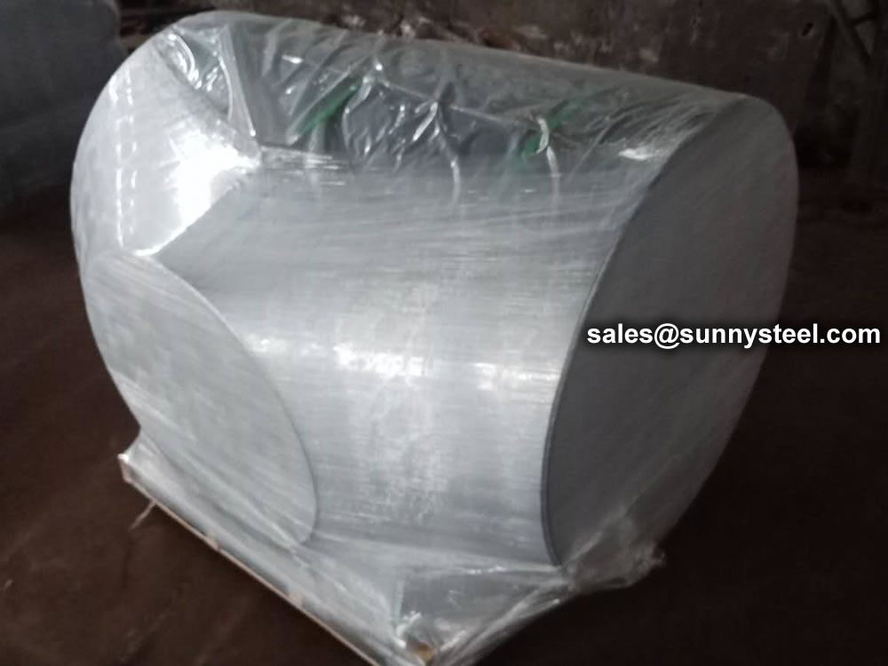
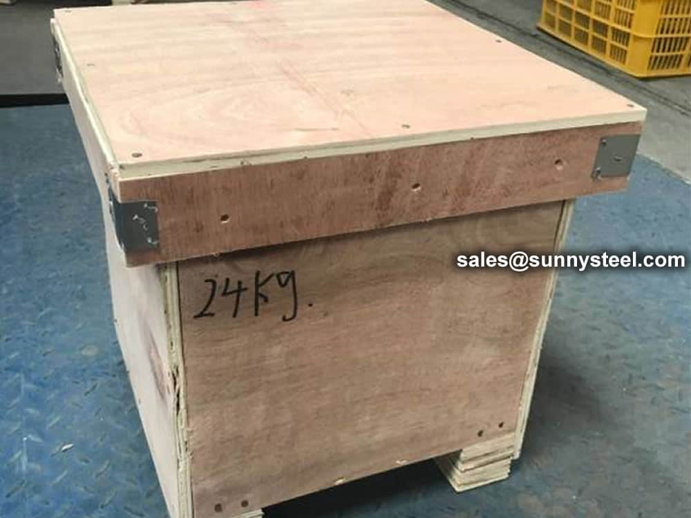
Packing
For packing of carbon steel flanges with painting,we would use the bubble wrap to protect the painting.For flanges without painting or oiled with long-term shipment,we would suggest client to use the anti-tarnish paper and plastic bag to prevent the rust. Packing reducers in wooden cases
Wrap the plastic tightly around the pipe to protect the tee
Inquiry
Need to inquire about our products? Fill out the form below and our staff will be in touch!
FAQ
Q: How long is your delivery time? A: The delivery time of customized products is generally 25 35 days, and non customized products are generally shipped within 24 hours after payment. Q: Do you provide samples? Is it free? A: If the value of the sample is low, we will provide it for free, but the freight needs to be paid by the customer. But for some high value samples, we need to charge a fee. Q: What are your payment terms? A: T/T 30% as the deposit,The balance payment is paid in full before shipment Q: What is the packaging and transportation form? A: Non steaming wooden box and iron frame packaging. Special packaging is available according to customer needs. The transportation is mainly by sea. Q: What is your minimum order quantity? A: There is no minimum order quantity requirement. Customized products are tailor made according to the drawings provided by the customer.


 en
en 

 Bevelled Ends
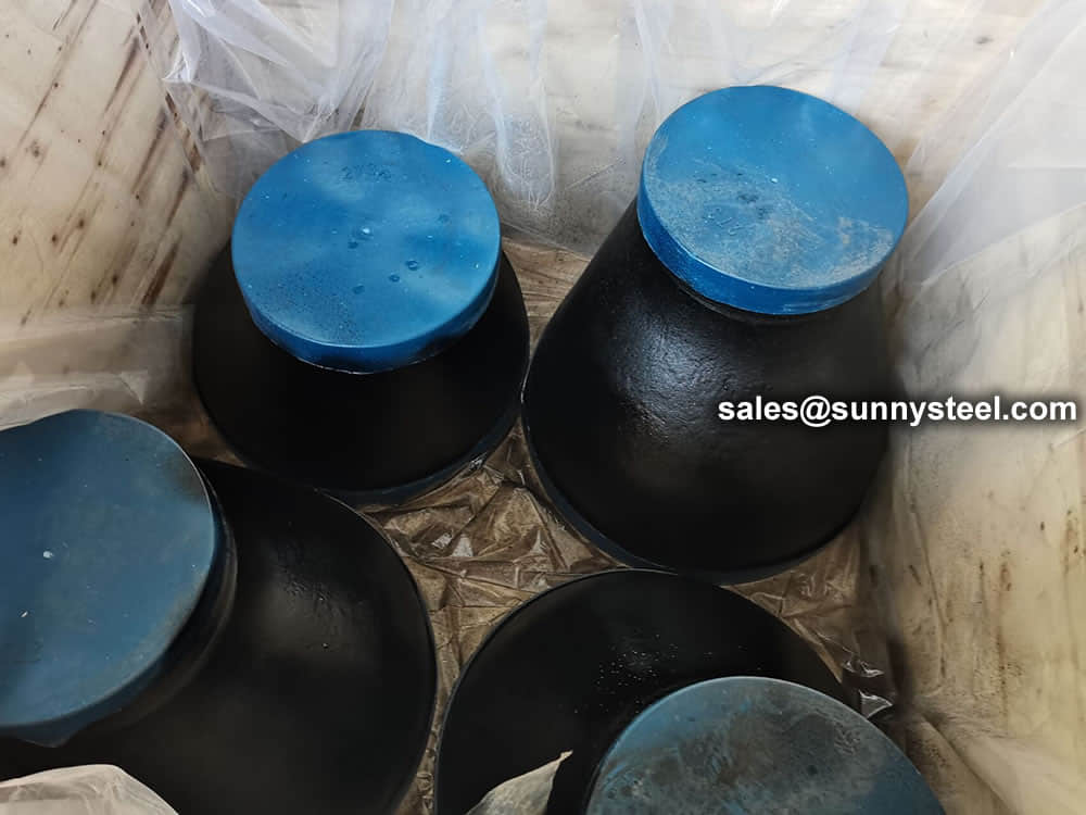 Packing reducers in wooden cases
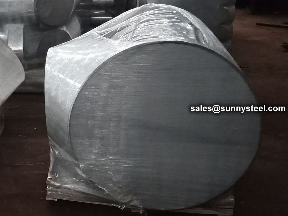


 Tiếng Việt
 Français
 Deutsch
 Русский
 Español
 Italiano
 Svenska
 العربية
 Português
 Bahasa Indonesia
 മലയാളം
 Malagasy
 Afrikaans
 Shqip
Shqip አማርኛ
አማርኛ Հայերեն
 Azərbaycan dili
 Euskara
 Беларуская мова
 বাংলা
বাংলা Bosanski
 Български
 Català
 Cebuano
 Chichewa
 繁體中文
繁體中文 Corsu
Corsu Hrvatski
 Čeština
 Dansk
Dansk Nederlands
 Esperanto
 Eesti
Eesti Filipino
 Suomi
Suomi Frysk
Frysk Galego
 ქართული
 Ελληνικά
 ગુજરાતી
 Kreyol ayisyen
 Harshen Hausa
 Ōlelo Hawaiʻi
 עִבְרִית
 हिन्दी
 Hmong
Hmong Magyar
 Íslenska
 Igbo
Igbo 日本語
日本語 Gaeilge
 Basa Jawa
 ಕನ್ನಡ
ಕನ್ನಡ Қазақ тілі
 ភាសាខ្មែរ
 한국어
한국어 كوردی
كوردی Кыргызча
 ພາສາລາວ
 Latin
Latin Latviešu valoda
 Lietuvių kalba
 Lëtzebuergesch
 Македонски јазик
 Bahasa Melayu
 Maltese
 Te Reo Māori
 मराठी
मराठी Монгол
 ဗမာစာ
ဗမာစာ नेपाली
 Norsk bokmål
 پښتو
پښتو فارسی
فارسی Polski
 ਪੰਜਾਬੀ
 Română
 Samoan
 Gàidhlig
 Српски језик
 Sesotho
 Shona
Shona سنڌي
سنڌي සිංහල
සිංහල Slovenčina
 Slovenščina
 Afsoomaali
 Basa Sunda
 Kiswahili
 Тоҷикӣ
 தமிழ்
தமிழ் తెలుగు
 ไทย
ไทย Türkçe
 Українська
 اردو
اردو O‘zbekcha
 Cymraeg
 isiXhosa
 יידיש
יידיש Yorùbá
 Zulu
Zulu