Our team is highly trained and experienced in servicing and producing all types of steel supplies. Need help or have a question?
sales@abrasionresistantpipe.com
Tel.: +8621-3378-0199
Our team is highly trained and experienced in servicing and producing all types of steel supplies. Need help or have a question?
sales@abrasionresistantpipe.com
Tel.: +8621-3378-0199

Low alloy U bent tube is a type of tubing that is made from low alloy steel and is bent into a U shape.
Low alloy U bent tube is a type of tubing that is made from low alloy steel and is bent into a U shape.
The semi-finished product for U bend tubes are heat exchanger tubes, manufactured and supplied according to DIN 28180 and ASTM A179.
Tubes for heat exchangers are made of steel according to:
| Standard | Application |
| ASTM A179 | Seamless Cold-Drawn Low-Carbon Steel Heat-Exchanger and Condenser Tubes |
| ASTM A192 | Seamless Carbon Steel Boiler Tubes for High-Pressure Service |
| ASTM A210 | Seamless Medium-Carbon Steel Boiler and Superheater Tubes |
| ASTM A213 | seamless Ferritic and Austenitic Alloy-Steel Boiler, Superheater, and Heat-Exchanger Tubes |
| ASTM A334 | Seamless Steel Pipe for Low-Temperature Service and other Applications with Required Notch Toughness |
| JIS G3461/2 | carbon steel tubes used for heat exchange in boilers, heat exchangers, condensers, and similar equipment |
| EN10216-1/2 | specified the standard of cold processed precision steel tubes in a wide range of sizes |
| DIN17175 | seamless tubes for high-pressure and high-temperature applications, specifically for boilers and heat exchangers |
| Standard | Grade | Chemical Components (%) | Mechanical Properties | ||||||||||
| C | Si | Mn | P | S | Mo | Cr | V | T.S. (Mpa) | Y.S. (Mpa) | E.L. (%) |
Hardness (HRB) |
||
| ASME SA179 | SA179 | 0.06-0.18 | / | 0.27-0.63 | ≤0.035 | ≤0.035 | / | / | / | ≥325 | ≥180 | ≥35 | ≤72 |
| ASME SA192 | SA192 | 0.06-0.18 | ≤0.25 | 0.27-0.63 | ≤0.035 | ≤0.035 | / | / | / | ≥325 | ≥180 | ≥35 | ≤77 |
| ASME SA210 | A1 | ≤0.27 | ≥0.10 | ≤0.93 | ≤0.035 | ≤0.035 | / | / | / | ≥415 | ≥255 | ≥30 | ≤79 |
| C | ≤0.35 | ≥0.10 | 0.29-1.06 | ≤0.035 | ≤0.035 | / | / | / | ≥485 | ≥275 | ≥30 | ≤89 | |
| ASTM A333 /A334 | GR.1 | ≤0.30 | / | 0.4-1.06 | ≤0.025 | ≤0.025 | / | / | / | ≥380 | ≥205 | ≥35 | -45° |
| GR.6 | ≤0.30 | ≥0.10 | 0.29-1.06 | ≤0.025 | ≤0.025 | / | / | / | ≥415 | ≥240 | ≥30 | -45° | |
| GR.8 | ≤0.13 | 0.13-0.32 | ≤0.90 | ≤0.025 | ≤0.025 | / | / | 8.40-9.60 | ≥690 | ≥515 | ≥22 | -195° | |
U bend tubes for heat exchangers applied mostly in oil and gas plants, chemical and petrochemical plants, refineries, power plants and renewable energy plants. Low fin tubes can be supplied in the form of U bends.
U-bend tubes are widely used in heat-exchanger systems. Heat-exchanger equipment on the basis of seamless stainless U-tubes is essential in strategically important and critical fields — nuclear and petrochemical machine building.

| Item | Condition (when) | Tolercance |
|---|---|---|
| Ovality | Nominal bend radius ≤ 2 x nominal OD | less than or equal to 12% |
| 2 x nominal OD < Nominal bend radius ≤ 4 x nominal OD | less than or equal to 10% | |
| Nominal bend radius > 4 x nominal OD | less than or equal to 5% | |
| Nominal bend radius ≤ 2 x nominal OD | 0.75 x nominal wall | |
| Mimimum wall thickness | 2 x nominal OD < Nominal bend radius ≤ 4 x nominal OD | 0.8 x nominal wall |
| Nominal bend radius > 4 x nominal OD | 0.9 x nominal wall | |
| Nominal bend radius ≤ 8″ (200mm) | +/-3/64″(1mm) | |
| Bending Radius | 8″ (200mm) < Nominal bend radius ≤ 16″ (400mm) | +/-1/16″(1mm) |
| Nominal bend radius >16″ (400mm) | +/-5/64″(1mm) | |
| Disrance between legs | Max 1/16″(1.5mm) | |
| Wall thinning of bending area | Max 17% | |
| Difference between leg lengths at the ends | Leg length ≤ 16′ (4.88m) | +1/8″(3mm) |
| Leg length > 16′ (4.88m) | +3/16″(5mm) | |
| Deviation from plane of bend | ≤ 3/16″(1.5mm) | |
| Flattening on bend | ≤ 10% nominal diameter | |
| Straight leg length | ≤5m | +1/8″(3mm) |
| >5m | +3/16(5mm) | |
| Total tube length including radius | ≤6m | +3/16(5mm) |
| >6m | +5/16″(8mm) |
The purpose of the U bend in the tube is to allow for easy installation and routing of fluid or gas in a piping system, without the need for additional fittings or connections. Low alloy steel is used in these tubes because it has a lower cost compared to stainless steel, and is suitable for applications where corrosion resistance is not critical. These tubes are commonly used in industrial, oil and gas, and petrochemical industries for heat exchangers, boilers, and condensers.
Low alloy U-bent tubes are a type of heat exchanger tube that are made from low alloy steel and are bent into a U-shape to fit into heat exchanger units. They are designed to withstand high temperatures and pressures, making them ideal for use in industrial applications.
U bending tube is carried out by cold working method and is being done to the necessary bend radius as per client drawings. U-bend tube/pipe can be manufactured from an extensive range of pipe materials that contain high and low yield stainless steels, alloy steels, carbon steels,Monel , Inconel, hastelloy,duplex , super duplex,titanium,copper alloy and Cr-Ni alloys. Usually U-bends manufactured from seamless tube, can further be customized in terms of thicknesses and sizes as per the specific requirements of our clients. They are easy for further assemble tube bundles.

We provide U bend Tubes pipe in diverse industries for a range of applications such as in Boiler, Condensers, Super Heaters,tube bundles for Heat Exchangers, Coolers/Inter-coolers, Chiller, and so on. These are as well being used in dissimilar industries such as in Fertilizer Plants, Sugar Industry, Steel Plants,Oil & Gas plants, Chemical & Petrochemical plants, Refineries, Power plants, Renewable energy plants etc.
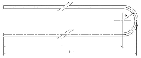 The semi-finished product for U bend tubes are heat exchanger tubes, manufactured and supplied according to DIN 28180 and ASTM A179. Tubes for heat exchangers are made of steel according to:
other types of steel can be supplied by agreement.
U bend tubes for heat exchangers applied mostly in oil and gas plants, chemical and petrochemical plants, refineries, power plants and renewable energy plants. Low fin tubes can be supplied in the form of u bends.
Post bending heat treatment by electrical resistance (Joule effect) is applied. The temperature is monitored and controlled during the process. It is possible to perform the heat treatment in a nitrogen atmosphere.
Heat Treatment Equipment
Sizes tolerances of U bend tubes are to fulfil the requirements of: ASTM A556 / 556M and DIN 28 179
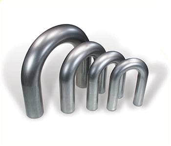
‘U’ bends are produced, controlled and measured fully in accordance with relevant standards.
Material / Grade
 Here is a list for providing ovality, minimum wall thickness, bending radius, distance between legs, wall thinning of bending area and so on. Thus, we can figure out which kind of type would be our final choice for our engineering project.
| Item | Condition (when) | Tolercance |
|---|---|---|
| Nominal bend radius ≤ 2 x nominal OD | less than or equal to 12% | |
| Ovality | 2 x nominal OD < Nominal bend radius ≤ 4 x nominal OD | less than or equal to 10% |
| Nominal bend radius > 4 x nominal OD | less than or equal to 5% | |
| Nominal bend radius ≤ 2 x nominal OD | 0.75 x nominal wall | |
| Mimimum wall thickness | 2 x nominal OD < Nominal bend radius ≤ 4 x nominal OD | 0.8 x nominal wall |
| Nominal bend radius > 4 x nominal OD | 0.9 x nominal wall | |
| Nominal bend radius ≤ 8" (200mm) | +/-3/64"(1mm) | |
| Bending Radius | 8" (200mm) < Nominal bend radius ≤ 16" (400mm) | +/-1/16"(1mm) |
| Nominal bend radius >16" (400mm) | +/-5/64"(1mm) | |
| Disrance between legs | Max 1/16"(1.5mm) | |
| Wall thinning of bending area | Max 17% | |
| Difference between leg lengths at the ends | Leg length ≤ 16' (4.88m) | +1/8"(3mm) |
| Leg length > 16' (4.88m) | +3/16"(5mm) | |
| Deviation from plane of bend | ≤ 3/16"(1.5mm) | |
| Flattening on bend | ≤ 10% nominal diameter | |
| Straight leg length | ≤5m | +1/8"(3mm) |
| >5m | +3/16(5mm) | |
| Total tube length including radius | ≤6m | +3/16(5mm) |
| >6m | +5/16"(8mm) |
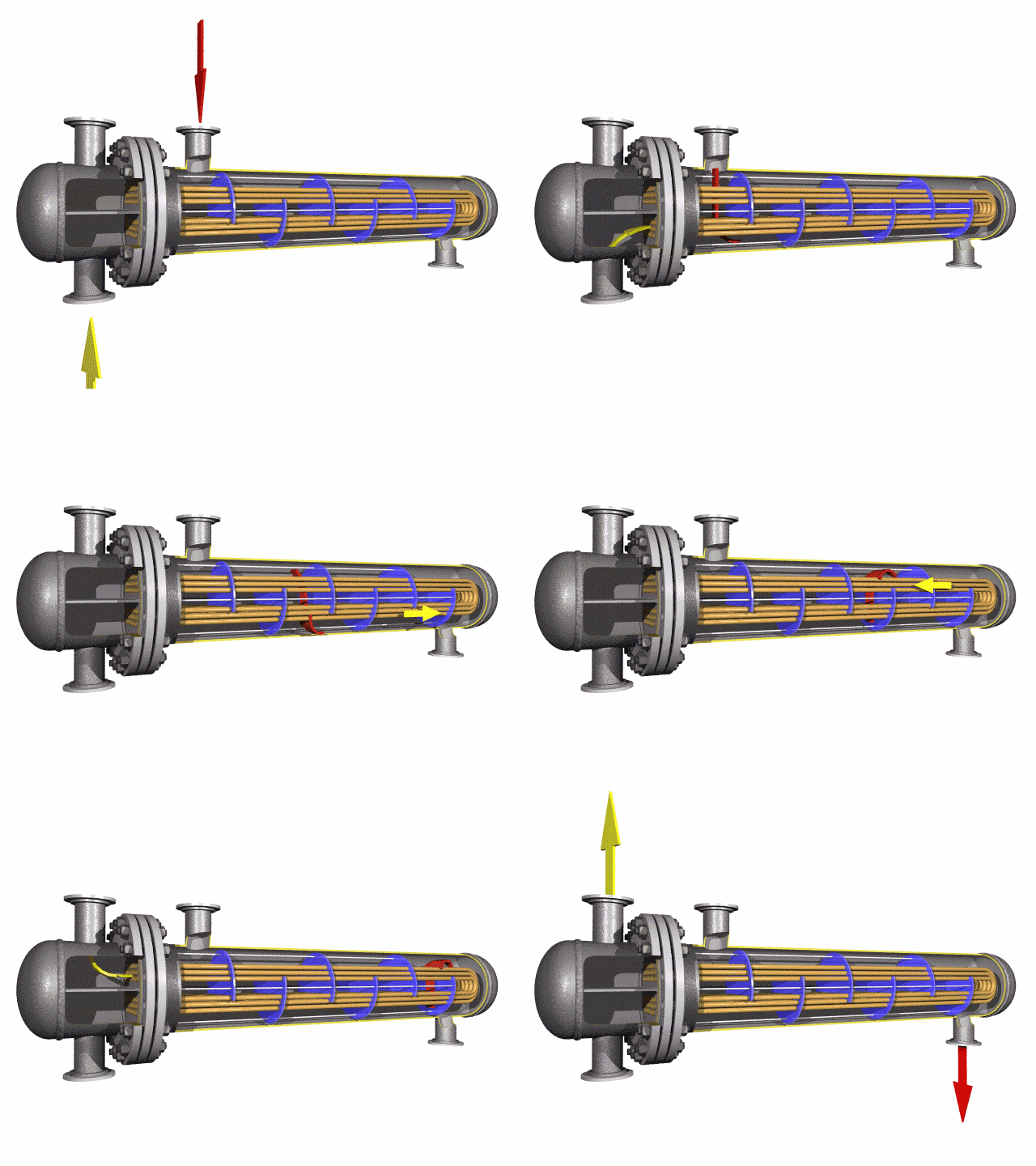
U-bend tubes are widely used in heat-exchanger systems.
Heat-exchanger equipment on the basis of seamless stainless U-tubes is essential in strategically important and critical fields — nuclear and petrochemical machine building.
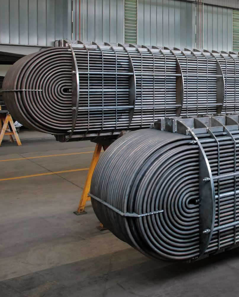
U tube heat exchanger is characterized by its simple structure, good tightness, convenient maintenance and cleaning, low cost, good thermal compensation performance and strong pressure bearing capacity. The U-tube heat exchanger has the largest heat exchange area under the same diameter. The main structure of U-shaped tube heat exchanger includes tube box, cylinder, head, heat exchange tube, nozzles, baffle, anti-shock plate and guide tube, anti-short circuit structure, support and other accessories of the shell and tube side, is the most commonly used in shell and tube heat exchanger.
Tube sheet
Tube sheet is one of the most important parts of shell – tube heat exchanger. The tube plate is the barrier between the shell side and the pipe side. When the heat exchange medium has no corrosion or slight corrosion, it is generally made of low carbon steel, low alloy steel or stainless steel. The connection form of tube-sheet and shell is divided into non-detachable and detachable types. The former is the connection between tube-sheet and shell in the fixed tube-sheet heat exchanger. The latter, such as U-shaped tube type, floating head type and stuffing box type and sliding tube plate type heat exchanger tube plate and shell connection. For removable connections, the tube plate itself is usually not in direct contact with the shell, but the flange is connected to the shell indirectly or is clamped by two flanges on the shell and the tube box.
Tube box
Most of the shell tube heat exchangers with larger shell diameters adopt tube and box structures. The tube box is located at both ends of the heat exchanger, which evenly distributes the fluid from the pipe to the heat exchanger tubes and gathers the fluid in the tubes together to send out the heat exchanger. In a multi-pipe shell, the casing can also change the flow direction. The structure of the tube box is mainly determined by whether the heat exchanger needs to be cleaned or whether the tube bundle needs to be divided.
Perhaps the best known use of tube sheets are as supporting elements in heat exchangers and boilers. These devices consist of a dense arrangement of thin walled tubes situated inside an enclosed, tubular shell. Tubes are supported on either end by sheets which are drilled in a predetermined pattern to allow the tube ends to pass through the sheet. The ends of the tubes which penetrate the tube sheet are expanded to lock them in place and form a seal. The tube hole pattern or “pitch” varies the distance from one tube to the other and angle of the tubes relative to each other and to the direction of flow. This allows the manipulation of fluid velocities and pressure drop, and provides the maximum amount of turbulence and tube surface contact for effective Heat Transfer.
In cases where it is critical to avoid fluid intermixing, a double tube sheet can be provided. The design of tube sheets is a fairly precise and complex process; the exact number of tubes needs to be established and a pattern of holes calculated to spreads them evenly over the tube sheet surface. Large exchangers may have several thousand tubes running through them arranged into precisely calculated groups or bundles. Sheet design and production is largely automated these days with computer software (like CAD) performing the calculations and the tube sheet drilling done on computer numerical control (CNC) machines. In this design, the outer tube sheet is outside the shell circuit, virtually eliminating the chance of fluid intermixing. The inner tube sheet is vented to atmosphere so any fluid leak is easily detected. Duwa Piping factory drilling department has professional drilling equipment and working team, we can provide the best quality tube sheet for you.
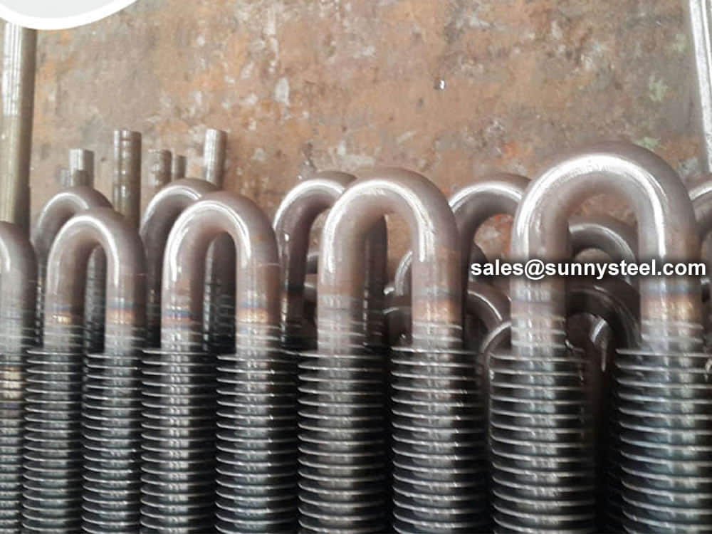
Fin tubes are used in applications involving the transfer of heat from a hot fluid to a colder fluid through a tube wall. Furthermore, finned tubes are used when the heat transfer coefficient on the outside of the tubes is appreciably lower than that on the inside.
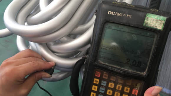
Before their shipment, we will conduct a comprehensive inspection. The inspection contains: size, thickness, length, radius and marking.
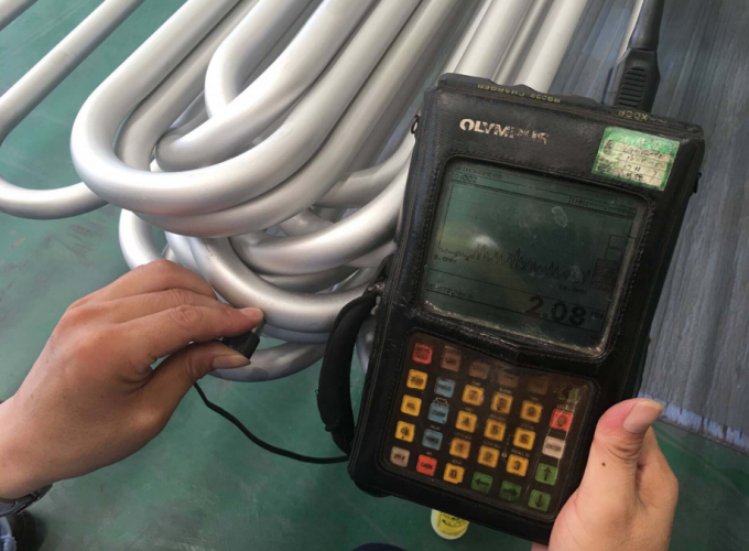
Size inspection
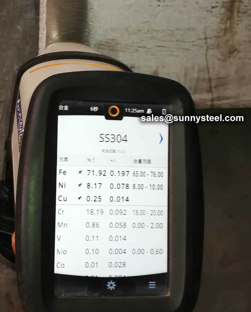
PMI test
Any type of packing U bend tubes is available according to customer need to worldwide destinations.
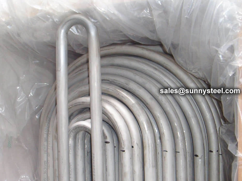
Stainless steel U bend tubes
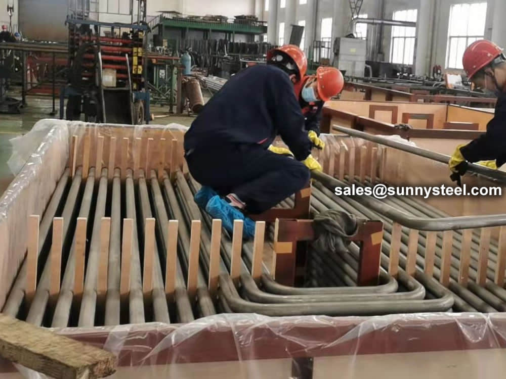
SA 213 TP347H stainless tubes
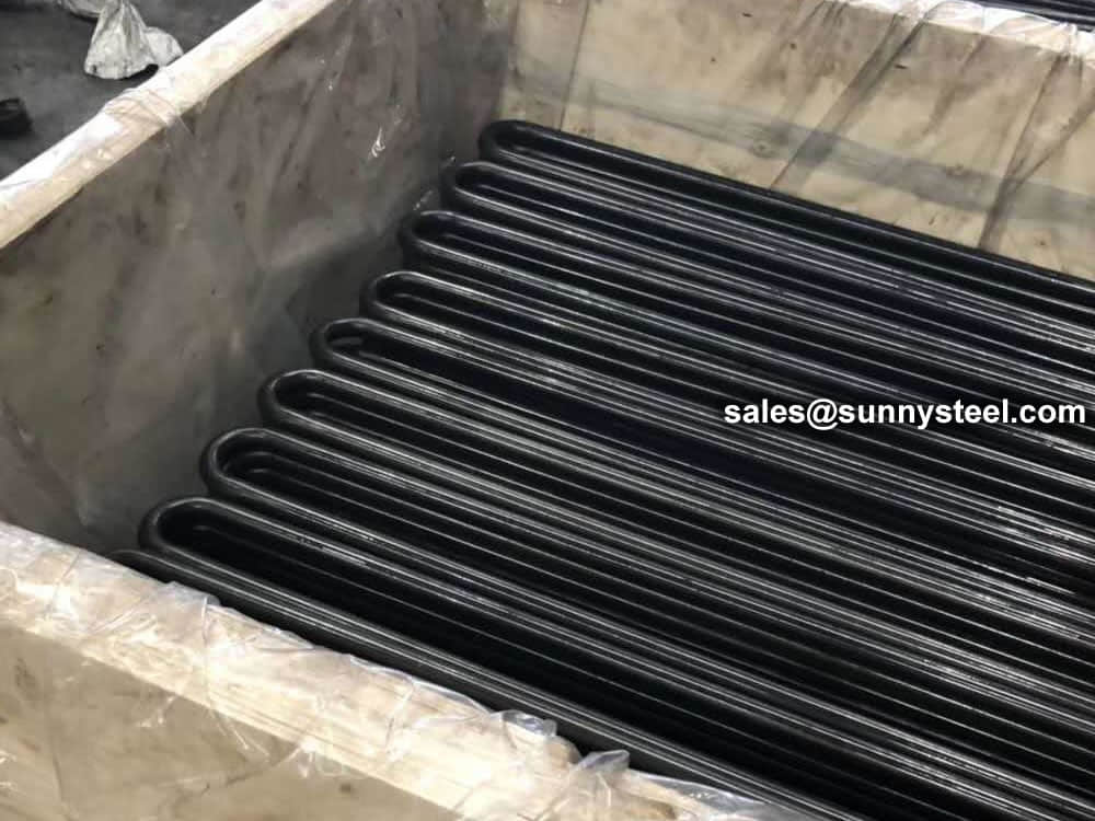
ASTM A179 U bend tubes
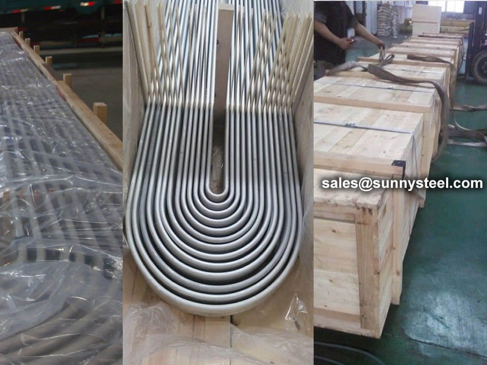
U bend tubes are packed in wooden cases
Need to inquire about our products? Fill out the form below and our staff will be in touch!
Q: How long is your delivery time?
A: The delivery time of customized products is generally 25 35 days, and non customized products are generally shipped within 24 hours after payment.
Q: Do you provide samples? Is it free?
A: If the value of the sample is low, we will provide it for free, but the freight needs to be paid by the customer. But for some high value samples, we need to charge a fee.
Q: What are your payment terms?
A: T/T 30% as the deposit,The balance payment is paid in full before shipment
Q: What is the packaging and transportation form?
A: Non steaming wooden box and iron frame packaging. Special packaging is available according to customer needs. The transportation is mainly by sea.
Q: What is your minimum order quantity?
A: There is no minimum order quantity requirement. Customized products are tailor made according to the drawings provided by the customer.