We use cookies to ensure that we give you the best experience on our website.
AWWA Flanges
AWWA Flange Standards differ from ANSI (American National Standards Institute) and ASME (American Society of Mechanical Engineers) certifications in a variety of ways, the most important being their specificity: AWWA standards evaluate properties that particularly affect potable water use, as opposed to broader industrial flange applications.
AWWA Flange Standards differ from ANSI (American National Standards Institute) and ASME (American Society of Mechanical Engineers) certifications in a variety of ways, the most important being their specificity: AWWA standards evaluate properties that particularly affect potable water use, as opposed to broader industrial flange applications. Our company provides an array of AWWA flanges to meet your application’s specifications.
WHAT IS AWWA?
The American Water Works Association, formed in 1881, was developed to identify and unify major requirements for waterworks systems. Today, the international association serves non-profit, educational, and scientific roles to improve and support water quality and supply around the world.
Members of AWWA include water treatment plant management and operations teams, water utility organizations, manufacturers, scientists and environmentalists, regulators, academics, and researchers in the fields of water supply and public health. North America alone is home to 43 distinct AWWA Sections.
AWWA’s standards program began in 1908 with development and research to support regulatory standards for products, processes, and best practices. This invaluable reference is now recognized globally as a key source for scientific and management insight for water supply.
AWWA Standards
With over 150 Standards, AWWA supports a full range of water supply practices, equipment, and components. In addition to AWWA Flange Standards, waterworks specialists will find AWWA support covering:
Water treatment chemicals
Filtration materials
Meters and measures
Disinfection practices
Valves
Storage tanks of all sizes
Utility management practices
Pumps
Pipe and Fittings
AWWA Certified Flange Types
Unlike ANSI and ASME standards, AWWA Flange Standards do not address welded auxiliary connections or tapping. They cover a very specific range of flange types, including:
Slip-on Ring and Hub Type Flanges, fitted over a pipe
Threaded Iron Flanges, fitted to externally threaded pipes
Material Grades and Performance
The AWWA Standards program covers pipes, flanges, and fittings in all manner of materials, including:
Plastic
Ductile iron
Steel and stainless steel
Concrete
Asbestos-cement
AWWA C207 does not require a specific grade of steel, so long as the flange meets minimum standards for physical and chemical properties. These properties include:
.05% Sulfur (maximum)
.04% Phosphorus (maximum)
.29% Carbon (maximum)
50,000 psi Tensile (minimum)
32,000 psi Yield (minimum)
Industries and Applications
The waterworks-specific AWWA Standard Flanges have been developed to meet light duty applications, typically requiring performance at or below 300 psi. The most common pressure range is AWWA Class D, rated at 175 psi for sizes under 12 inches and 150 psi for larger sizes.
Common applications of AWWA Flanges include:
Waterworks
Slurry
Waste water
Plant piping
AWWA Vs. ANSI Flange Standards
Both the AWWA and ANSI have thorough standards for flanges, and the two standards are different in several ways.
Both the AWWA and ANSI have thorough standards for flanges, and the two standards are different in several ways. AWWA standards provide flange properties intended for potable water use only. In contrast, ANSI standards are aimed at industrial flange applications.
For example, AWWA flange ratings are applicable only at atmospheric temperature, while ANSI ratings cover flange installations from -20°F to 1500°F. AWWA standards provide flange properties intended for potable water use only. In contrast, ANSI standards are aimed at industrial flange applications. For example, AWWA flange ratings are applicable only at atmospheric temperature, while ANSI ratings cover flange installations from -20°F to 1500°F.
ANSI covers numbered class flanges from 150 to 2500, and AWWA standards encompass lettered flange classes B, E, F, and the commonly used class D connection. AWWA provides ratings for a much broader range of nominal pipe sizes (3″-144″) than ANSI provides (1/2″-24″).
Finally, ANSI and AWWA flange standards differ in the breadth of applications discussed. ANSI includes information for welded auxiliary connections and tapping, while AWWA does not address those installations. Also, the AWWA standard only encompasses ring, hub type, blind flanges, and threaded iron flanges while the ANSI standard inlcudes all flange types.
This discussion on AWWA flange standards and ANSI flange standards is based on information from ANSI/AWWA C115/A21.15-99: “American National Standard for Flanged Ductile-Iron Pipe with Ductile-Iron or Gray-Iron Threaded Flanges”, ANSI/AWWA C207-94: “AWWA Standard for Steel Pipe Flanges for Waterworks Service-Sizes 4 In. Through 144 In.”, and ANSI B16.5-1981: “Pipe Flanges and Flanged Fittings”.
AWWA C207 Steel Pipe Flanges
AWWA C207 steel flanges are usually of a mild carbon steel or stainless variant and are most often either of the ring slip on or blind disc style. Due to their intended design, they do not have ring joint or raised faces, and are typically sealed with rubber gaskets. Due to their cost and weight compared to other flange types, they are also becoming more popular with project work for structural steel types which require mating or filling a gap between existing flanges.
More Specifically, the American Water Works Association has published specification C207 to provide a standard for carbon steel rings and blinds (and formerly, also hubs). The OD and bolt pattern matches that of B16.1 class 125 flanges. They will also match B16.5 class 150 flanges up to 24” nominal pipe size and B16.47 Series A up to 60” NPS. The main dimensional difference is thickness and the lack of a raised face or hub (except in legacy systems).
AWWA is slightly more lenient in what kind of steel can be used as well. C207 limits Carbon, Phosphorus, and Sulfur contents to 0.35%, 0.04%, and 0.05%, respectively. The lower minimum yield and tensile strength requirements (32ksi and 50ksi, respectively) allows several commercially abundant grades of carbon steel such as A36, A516-70, A181-60, A105. All AWWA flanges that Texas Flange supplies will have MTRs showing actual physical and chemical properties for each heat lot. When you do not have to meet ASME code, but need a large flange, send us your requirement for AWWA Ring or Blind flanges!
The AWWA C207 is an American National Standard for steel pipe flanges for waterworks service, sizes 4″ through 144″ (100 mm through 3600 mm). The AWWA is the abbreviation of “American Water Works Association”. The origin of AWWA C207 can be dated back to year 1942 when a paper proposing standards for slip-on steel-ring flanges for welding to steel water pipes. This standard was necessary because the lowest pressure ratings for steel flanges at that time were those having cold-water pressure ratings of 275 psi (1896 KPa). The ratings are far higher than those ordinarily needed for water service (150 psi / 1034 KPa) primary pressure rating.
Awwa C207 Flanges Class B Class D Class E Awwa Pipe Ring Flanges
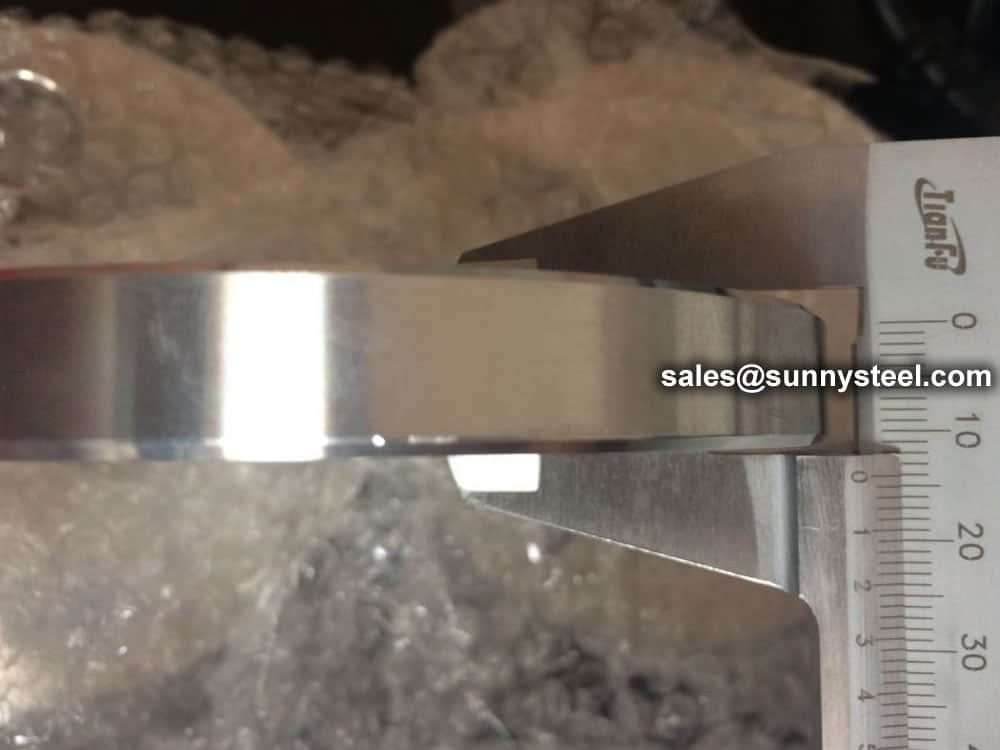
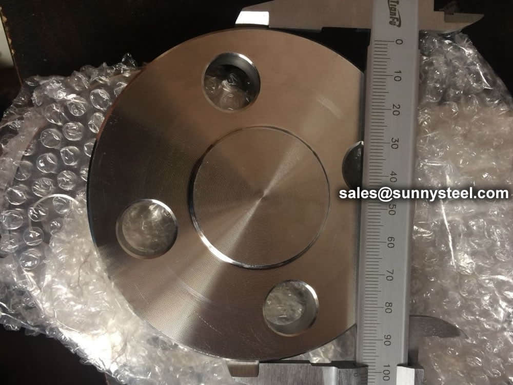
The AWWA C207 flanges are intended for attachment to steel pipes, fittings, valves or other appurtenances in water utility service. The standard has specified two general types of flange: (1) ring-type slip-on flanges, also known as ring flanges or plate flanges; (2) blind flanges. Both the ring flange and blind flange are steel flanges without hub. Besides, in Appendix B, it also provides additional information for dimensions of steel-hub flanges. The AWWA C207 flange can be further classified into four classes according to its working pressure limit: Class B (86 psi), Class D (175-150 psi), Class E (275 psi), Class F (300 psi). The pressure limits are for conditions and temperatures customary in water utility service.
Materials & Manufacture
The AWWA C207 steel pipe flanges shall be made from materials complying with the requirements of the Safe Drinking Water Act. Basically, the AWWA C207 flange shall be made from steel plate, bar or forgings conforming to the following requirements: (1) Specified minimum tensile strength = 50,000 psi [345 MPa]; (2) Specified minimum yield strength = 32,000 psi [221 MPa]; (3) Elongation, 2″ [50 mm] gauge length (minimum) = 18%, or 8″ [200 mm] gauge length (minimum) = 14%; (4) Carbon (maximum) = 0.35%; (5) Phosphorus (maximum) = 0.04%; (6) Sulfur (maximum) = 0.05%. The AWWA C207 flanges shall be furnished with bolts & studs made to ASTM A193 B7 and ASTM A194 2H heavy hex nuts or ASTM A563 heavy hex nuts for 1″ and smaller. Washers, when used, shall meet the requirements of ASTM F436. The flange gasket shall be furnished in full face type or ring type, made from rubber, compressed fiber, or PTFE, respectively.
Referring to manufacturing methods, AWWA C207 steel flanges may be made from seamless forgings, cut from plate as a single piece, welded bar rings, or segmented and welded plates. Small & medium size flanges are usually manufactured integrally by a forging or integral cutting process. When the O.D of a flange exceeds the width of available plate material (approx. 78″ [1950 mm] ID and larger), it shall be manufactured by welding maximum four segments and all welds shall be 100% X-ray inspected.
Dimensional Tolerances
Inside diameter of flange: +1/16″ [1.6 mm], -0; Outside diameter of flange: ±1/8″ [3.2 mm]; Thickness of flange 18″ [450 mm] and smaller: +1/8″ [3.2 mm], -0; Thickness of flange 20″ [500 mm] and larger: +3/16″ [4.8 mm], -0; Bolt circle diameter: ±1/16″ [1.6 mm]; Bolt hole spacing: ±1/32 [0.79 mm].
Facing and Drilling
AWWA C207 flanges of all classes and types shall be flat faced (FF) – that is without projection or raised face. Either a serrated concentric or serrated spiral finish having 24~55 grooves per inch (0.94~2.17 grooves per mm) shall be used. The cutting tool employed shall have a radius of 0.06 inch (1.52 mm) or larger. The resultant surface finish shall have a 125 to 500 μinch (3.2 to 12.7 μm) roughness average (Ra), as defined in B46.1. Flange faces shall be free of lining and coating materials, except that a removable corrosion inhibitor is permitted until installation. The gasket seating surface shall not have protrusions.
For flanges up to 84″ (2,100 mm) in diameter, bolt holes shall be drilled 1/8″ (3.2 mm) larger in diameter than the nominal diameter of the bolt. For flanges larger than 84″ (2,100 mm) in diameter, bolt holes shall be drilled 3/16″ (4.8 mm) larger than the nominal bolt diameter. Bolt holes may be over-sized by an additional 1/8″ (3.2 mm) to accommodate insulators or to facilitate alignment with the mating flange. If bolt holes are over-sized, washers shall be used.
Types
General flange types
Flanges mostly come in six different types. However, these designs can be modified to meet the specific functions and requirements of the applications. Therefore, it’s essential to understand the pressure at the flagged joint, the required strength, and the size of pipes involved. With the correct information comes six types of flanges that an individual can choose from. These include:
These flanges do not have a bore. It is used to blind off a flange or even a valve. When used at the end of a pipe or fitting, it provides an easy to open access for further extension of the pipe. The blind flange and its bolts are stressed more than any other flange.
This flange is used with a lap joint stub end fitting. It is similar to a slip-on flange, but with two differences. The radius and the flat face, both allow the flange to secure against the stub end fitting. This is useful where alignment of bolt holes is difficult, such as with spools to be attached to flanged nozzles of vessels. A lap joint is used in low pressure applications and not suitable where high external of heavy loads are present.
Slip-on flanges are designed to slip over the outside of pipe, long-tangent elbows, reducers, and swages. The flange has poor resistance to shock and vibration. It is easier to align than a weld neck flange. This flange is ideal for low pressure applications since the strength when under internal pressure is about one third that of a weld neck flange.
This is similar to a slip-on flange, except they have a bored and counter bore. The counter bore allows the pipe to fit into the socket/counter bore. The bore of the flange is the same diameter as the inside of the pipe. These flanges were first designed for small diameter, high pressure pipe.
It is similar to a slip-on Flange, but has internal threads. It is normally used for low pressure and not used where temperature or stress is very high.
This flange comes in two types, regular and long. The hub of the weld neck is designed to reduce the stress at the base of the flange. Regular weld neck flanges are used with buttweld fittings and long weld neck flanges are usually used with equipment and vessel nozzles. A long weld neck flange is rarely used with pipe. Both types of flanges are bored to match the inside diameter of the pipe or fitting to which it will be welded to. They are suitable where high pressure, extreme temperatures, shear impact and vibratory stresses apply.
Specialty flange types
Additionally, the flanges can be modified to form other types, depending on application and functions. These unique designs are made to incorporate specific needs and applications, like reducing flanges to answer to size and orifice flanges to incorporate orifice mounting.
Other examples in this category include:
A spectacle flange is a specialty flange made of two metal discs attached in the middle by a small section of steel. Spectable flanges get their name because they look like a pair of reading glasses, or spectacles.
Orifice flanges are for metering the volumetric flow rate of liquids and gasses through a pipe. This flange is normally available in weld neck, slip-on, and threaded flanges.
Our experts are exceptional at machining custom flanges for life. We have experience helping engineers, estimators, purchasing agents and more with their custom flanges.
An anchor flange is a device to restrain pipe movement in a piping system,it looks like a weld neck flange but has two hubs on the both sides to weld with the pipes,but there is no bolt bores on the anchor flanges.
Standard Connection Flange
This flange is normally used for nozzles on pressure vessels and rarely used with pipe.
Categorizing pipe flanges
The most common way of classifying flanges is by considering their shapes. However, it’s essential to understand that there are other ways to categorize flanges, as these come in handy when durability, functionality, and application are in question. These include:
Classification by material used includes brass, alloy steel, cast iron, carbon steel, stainless steel, aluminum, or PVC.
Classification by flange face includes flat, ring joint, raised, female and male, lap joint, tongue, and groove.
Classification by piping flange dimensions, which include pressure rating or nominal size.
Classification by flange finish, which gives smooth, stock, or serrated.
Flange Types in three groups
Remember the types of flanges described in the beginning of this article? (Welding Neck, Slip-On, Threaded, Socket Weld, Lap-Joint and Blind), well those were the standard types, now you’ll see that the types of flanges available in the type of the flange is very similar to them, so all the “pros” and “cons” described there can be applied here.
The types divided the flanges in three groups: loose, integral and optional. Below I’ll describe these types according to the Code.
Loose Type Flanges:
This type covers those designs in which the flange has no direct connection to the nozzle neck, vessel, or pipe wall, and designs where the method of attachment is not considered to give the mechanical strength equivalent of integral attachment.
Integral Type Flanges:
This type covers designs where the flange is cast or forged integrally with the nozzle neck, vessel or pipe wall, butt welded thereto, or attached by other forms of arc or gas welding of such a nature that the flange and nozzle neck, vessel or pipe wall is considered to be the equivalent of an integral structure. In welded construction, the nozzle neck, vessel, or pipe wall is considered to act as a hub.
Optional Type Flanges:
This type covers designs where the attachment of the flange to the nozzle neck, vessel or pipe wall is such that the assembly is considered to act as a unit, which shall be calculated as an integral flange, except that for simplicity the designer may calculate the construction as a loose type flange provided none of the following values is exceeded: g0 = 5/8″ (16 mm), B/g0 = 300, P = 300 psi (2 MPa) and operating temperature = 700°F (370°C).
Standards
Pipe Flange Standards mainly include three systems in the world, ANSI/ASME flange system(American), DIN flange system(European system), JIS flange system, other system made according to this three systems, like GB flange standard, which mainly made according to ANSI/ASME and DIN flange standard, Duwa Piping supplies those flanges with top quality and soonest delivery time.
ASME standards
ASME B16.1 – Gray Iron Pipe Flanges and Flanged Fittings: Classes 25, 125, and 250
ASME B16.5 – Pipe Flanges and Flanged Fittings: NPS 1/2 through NPS 24 Metric/Inch Standard
ASME B16.20 – Ring Joint Gaskets and Grooves for Steel Pipe Flanges
ASME B16.21 – Nonmetallic Flat Gaskets for Pipe Flanges
ASME B16.24 – Cast Copper Alloy Pipe Flanges and Flanged Fittings: Classes 150, 300, 600, 900, 1500, and 2500
ASME B16.34 – Large Diameter Steel Flanges (NPS 26 through NPS 60)
ASME B16.36 – Orifice Flanges
ASME B16.42 – Ductile Iron Pipe Flanges and Flanged Fittings: Classes 150 and 300
ASME B16.47 – Large Diameter Steel Flanges (NPS 26 Through NPS 60)
ASTM standards
ASTM A105 – Specification for Carbon Steel Forgings for Piping Applications
ASTM A182 – Specification for Forged or Rolled Alloy Steel Pipe Flanges, Forged Fittings, and Valves and Parts for High Temperature Service
ASTM A193 – Specification for Alloy Steel and Stainless Steel Bolting Materials for High Temperature Service
ASTM A194 – Specification for Carbon and Alloy Steel Nuts for Bolts for High Pressure and High Temperature Service
ASTM A694 – Specification for Carbon and Alloy Steel Forgings for Pipe Flanges, Fittings, Valves, and Parts for High-Pressure Transmission Service
ASTM A707 – Specification for Flanges, Forged, Carbon and Allow Steel for Low Temperature Service
AWWA standards
AWWA C115 – Standard for Flanged Ductile Iron Pipe with Ductile-Iron or Gray-Iron Threaded Flanges
ISO standards
ISO 5251 – Stainless steel butt-welding fittings
MSS standards
MSS SP-6 – Standard Finishes for Contact Faces Pipe Flanges and Connecting End Flanges of Valves and Fittings
MSS SP-9 – Spot Facing for Bronze, Iron and Steel Flanges
MSS SP-25 – Standard Marking Systems for Valves, Fittings, Flanges, and Unions
MSS SP-44 – Steel Pipeline Flanges
MSS SP-53 – Quality Standards for Steel Castings and Forgings for Valves, Flanges and Fittings and Other Piping Components – Magnetic Particle
MSS SP-54 – Quality Standards for Steel Castings and for Valves, Flanges and Fittings and Other Piping Components – Radiographic
MSS SP-55 – Quality Standards for Steel Castings and for Valves, Flanges and Fittings and Other Piping Components – Visual
MSS SP-75 – High Test Wrought Butt Welding Fittings
MSS SP-106 – Cast Copper Alloy Flanges and Flanged Fittings Class 125,150, and 300
ASME B16.5 and ASME B16.47 cover pipe flanges up to NPS 60 (B16.5 from 1/2″ to 24″ and B16.47 from 26″ to 60″). ANSI B16.47 covers two series of flanges, Series A is equal to MSS SP-44-44, and Series B is equal to API 605 (API 605 has been canclled).
Classes
Only the most used flange classes are listed on this page. For more information on flanges and their respective standards, please follow the link below.
150 300 400600900 1500 2500
The concept of flange ratings likes clearly. A Class 300 flange can handle more pressure than a Class 150 flange, because a Class 300 flange are constructed with more metal and can withstand more pressure. However, there are a number of factors that can impact the pressure capability of a flange.
The Pressure Class or Rating for flanges will be given in pounds. Different names are used to indicate a Pressure Class.
For example: 150 Lb or 150 Lbs or 150# or Class 150, all are means the same.
ASME B16.5 covers flanges with a nominal size from 1/2″ through 24″. It also includes classes from ANSI 150 through ANSI 2500. The flanges included in B16.5 are blind, lap joint, socket, slip-on, threaded and weld neck flanges.
ASME B16.47 covers flange with a nominal size of 24″ and larger. The flange classes it covers are from ANSI 75 through ANSI 900. The flanges included are blind and weld neck flanges. Additionally, B16.47 has two series of flanges, Series A (similar to ASME MSS SP44) & Series B (similar to API 605). Series A flanges are larger, heavier and have fewer bolt holes. The reason for series A and series B is that both specifications mentioned before were brought together to be covered under ASME B16.47.
Facing
There are three primary types of flange facings. Not all facings are available with each end connection. This is based on the design of the flange and design of the piping system.
The typical flange facings are:
Raised Face Flanges (RF)
Raised face flange has a small portion around the bore is raised from the face. The gasket seat on this raised face. The height of the raised face depends on the flange pressure-temperature rating that is known as a class of the flange. For 150# & 300# height of the raised face is 1/6” and above 300# it is 1/4”. The inside bore circle type of gasket is used with a raised face flange.
Flat Face Flanges (FF)
As the name suggests, the flat face flange has a flat face. Flat face flanges are used when the counter-flanges are flat faces. This condition occurs mainly in connection to Cast Iron equipment, valves, and specialties. A full-face gasket is used when a flat face flange is used.
Ring Type Joint Flanges (RTJ)
Ring joint type face flange has a specially designed grove in which metal gasket seat. This type of flange is used in high pressure and temperature services.
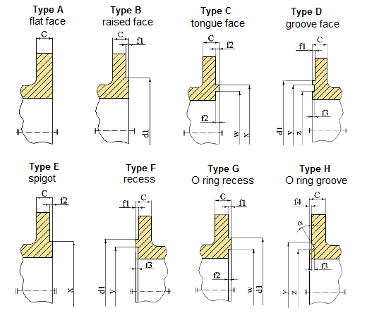
Flange facing types according to DIN EN 1092-1
Flanges and their joints – Circular flanges for pipes, valves, fittings and accessories, PN designated – Part 1: Steel flanges
This European standard specifies requirements for circular steel flanges in PN designations PN 2,5 to PN 400 and nominal sizes from DN 10 to DN 4000. This standard specifies the flange types and their facings, dimensions, tolerances, threading, bolt sizes, flange face surface finish, marking, materials, pressure/ temperature ratings and flange masses.
Flange faces have to be smooth enough to ensure a tight, leak-free seal for bolted flanges.
Type A: flat face
Type D: groove face
Type G: O Ring recess
Type B: raised face
Type E: spigot
Type H: O Ring groove
Type C: tongue face
Type F: recess
Flange facing dimensions
DN
PN
f1
f2
f3
f4
w
x
y
z
α
R
2.5
6
10
16
25
40
63
100
160
250
320
400
d1
10
35
35
40
40
40
40
40
40
40
40
40
40
2
4.5
4
2
24
34
35
23
-
2.5
15
40
40
45
45
45
45
45
45
45
45
45
45
29
39
40
28
-
20
50
50
58
58
58
58
58
58
58
58
58
58
36
50
51
35
41º
25
60
60
68
68
68
68
68
68
68
68
68
68
43
57
58
42
32
70
70
78
78
78
78
78
78
78
78
78
78
51
65
66
50
40
80
80
88
88
88
88
88
88
88
88
88
88
3
61
75
76
60
50
90
90
102
102
102
102
102
102
102
102
102
102
73
87
88
72
65
110
110
122
122
122
122
122
122
122
122
122
122
95
109
110
94
80
128
128
138
138
138
138
138
138
138
138
138
138
106
120
121
105
100
148
148
158
158
162
162
162
162
162
162
162
162
5
4.5
2.5
129
149
150
128
32º
3
125
178
178
188
188
188
188
188
188
188
188
188
188
155
175
176
154
150
202
202
212
212
218
218
218
218
218
218
218
218
183
203
204
182
200
258
258
268
268
278
285
285
285
285
285
285
285
239
259
260
238
250
312
312
320
320
335
345
345
345
345
345
345
-
292
312
313
291
300
365
365
370
378
395
410
410
410
410
-
-
-
4
343
363
364
342
350
415
415
430
438
450
465
465
465
-
-
-
-
5.5
5
3
395
421
422
394
27º
3.5
400
465
465
482
490
505
535
535
535
-
-
-
-
447
473
474
446
450
520
520
532
550
555
560
560
560
-
-
-
-
497
523
524
496
500
570
570
585
610
615
615
615
615
-
-
-
-
349
375
376
548
600
670
670
685
725
720
735
735
-
-
-
-
-
5
649
675
676
648
700
775
775
800
795
820
840
840
-
-
-
-
-
751
777
778
750
800
880
880
905
900
930
960
960
-
-
-
-
-
856
882
883
855
900
980
980
1005
1000
1030
1070
1070
-
-
-
-
-
961
987
988
960
1000
1080
1080
1110
115
1140
1180
1180
-
-
-
-
-
6.5
6
4
1062
1092
1094
1060
28º
4
1200
1280
1295
1330
1330
1350
1380
1380
-
-
-
-
-
1262
1292
1294
1260
1400
1480
1510
1535
1530
1560
1600
-
-
-
-
-
-
1462
1492
1494
1460
1600
1690
1710
1760
1750
1780
1815
-
-
-
-
-
-
1662
1692
1694
1660
1800
1890
1920
1960
1950
1985
-
-
-
-
-
-
-
1862
1892
1894
1860
2000
2090
2125
2170
2150
-
-
-
-
-
-
-
-
2062
2092
2094
2060
2200
2295
2335
2370
-
-
-
-
-
-
-
-
-
-
-
-
-
-
-
-
-
-
2400
2495
2545
2570
-
-
-
-
-
-
-
-
-
-
-
-
-
-
-
-
-
-
2600
2695
2750
2780
-
-
-
-
-
-
-
-
-
-
-
-
-
-
-
-
-
-
2800
2910
2960
2000
-
-
-
-
-
-
-
-
-
-
-
-
-
-
-
-
-
3000
3110
3160
3210
-
-
-
-
-
-
-
-
-
-
-
-
-
-
-
-
-
-
3200
3310
3370
-
-
-
-
-
-
-
-
-
-
-
-
-
-
-
-
-
-
-
3400
3510
3580
-
-
-
-
-
-
-
-
-
-
-
-
-
-
-
-
-
-
-
3600
3720
3790
-
-
-
-
-
-
-
-
-
-
-
-
-
-
-
-
-
-
-
3800
3920
-
-
-
-
-
-
-
-
-
-
-
-
-
-
-
-
-
-
-
-
4000
4120
-
-
-
-
-
-
-
-
-
-
-
-
-
-
-
-
-
-
-
-
units [mm]
Flange facing types C, D, E, F, G and H are not used for PN 2,5 and PN 6.
Flange facing types G and H are only used for PN 10 to PN 40.
The type of forged flange and sealing face for flange
Flanges provide the necessary connections to link pipelines. Faces are the mating surface of a flange.
Different types of flange faces are used as the contact surfaces to seat the sealing gasket material.
The type of flange
The type of sealing face
Pressure Class(PN,MPA)
Plate flange(PL)
Raise Face(RF)
0.25-2.5
Flat Face( FF)
0.25-1.6
Slip on flange(SO)
Raise Face(RF)
0.6-4.0
Flat Face( FF)
0.6-1.6
male and female face (MFM)
1.0-4.0
Tongue and groove face (TG)
1.0-4.0
Welding Neck Flange(WN)
Raise Face(RF)
1.0-25.0
male and female face (MFM)
1.0-16.0
Tongue and groove face (TG)
1.0-16.0
Ring Joint Face(RTJ)
6.3-25.0
Flat Face( FF)
1.0-1.6
Integral type flange(IF)
Raise Face(RF)
0.6-25.0
male and female face (MFM)
1.0-16.0
Tongue and groove face (TG)
1.0-16.0
Ring Joint Face(RTJ)
6.3-25.0
Flat Face( FF)
0.6-1.6
Socket Weld Flange(SW)
Raise Face(RF)
1.0-10.0
male and female face (MFM)
1.0-10.0
Tongue and groove face (TG)
1.0-10.0
Thread Flange(Th)
Raise Face(RF)
0.6-4.0
Flat Face( FF)
0.6-1.6
Lap joint Flange(LP)
Raise Face(RF)
0.6-1.6
male and female face (MFM)
1.0-1.6
Tongue and groove face (TG)
1.0-1.6
Blind flange(BL)
Raise Face(RF)
0.25-25.0
male and female face (MFM)
1.0-16.0
Tongue and groove face (TG)
1.0-16.0
Ring Joint Face(RTJ)
6.3-25.0
Flat Face( FF)
0.25-1.6
Other flange facings covered by these standards include the large and small tongue-and-groove facings, and the ring joint facing specifically for ring joint type metal gaskets.
Materials
Flanges are welded to pipe and equipment nozzle. Accordingly, it is manufactured from the following materials;
Carbon steel
Low alloy steel
Stainless steel
Combination of Exotic materials (Stub) and other backing materials
The list of materials used in manufacturing is covered in ASME B16.5 & B16.47.
ASME B16.5 -Pipe Flanges and Flanged Fittings NPS ½” to 24”
ASME B16.47 -Large Diameter Steel Flanges NPS 26” to 60”
ASTM standards define the specific manufacturing process of the material and determine the exact chemical composition of pipes, fittings and flanges, through percentages of the permitted quantities of carbon, magnesium, nickel, etc., and are indicated by "Grade".
The usual materials of flanges include stainless steel, carbon steel, aluminum and plastic. The choice of the material largely depends on the purpose of the flange. For example, stainless steel is more durable and is necessary for heavy use. On the other hand, plastic is more feasible for use in the home because of its reasonable price and easy installation. The materials used for flanges are under the designation of the American Society of Mechanical Engineers.
Flange materials acc. to ASTM
The most common materials for pipe flanges (forged grades) are: ASTM A105 (carbon steel high temperature to match A53/A106/API 5L pipes), A350 Grades LF1/2/3 (carbon steel low temperature to match A333 pipes), A694 Grades F42 to F80 (high yield carbon steel to match API 5L pipe grades), ASTM A182 Grades F5 to F91 (alloy steel flanges to match A335 pipes), A182 Grade F304/316 (stainless steel flanges to match A312 SS pipes), A182 Gr. F44/F51/F53/F55 (duplex and super duplex to match A790/A928 pipes) and various nickel alloy grades (Inconel, Incoloy, Hastelloy, Monel).
The material qualities for these flanges are defined in the ASTM standards.
What are ASTM Grades?
For example, a carbon steel pipe can be identified with Grade A or B, a stainless-steel pipe with Grade TP304 or Grade TP321, a carbon steel fitting with Grade WPB etc.
Chemical Composition (%) of ASTM A403
Steel No.
Type
C
Si
S
P
Mn
Cr
Ni
Mo
Other
ób
ós
δ5
WP304
0.08
1
0.03
0.045
2
18-20
8-11
515
205
28
WP304H
0.04-0.1
1
0.03
0.045
2
18-20
8-11
515
205
28
WP304L
0.035
1
0.03
0.045
2
18-20
8-13
485
170
28
WP304LN
0.03
0.75
0.03
0.045
2
18-20
8-10.5
N2:0.1-0.16
515
205
28
WP304N
0.08
0.75
0.03
0.045
2
18-20
8-11
N2:0.1-0.16
550
240
28
WP309
0.15
1
0.03
0.045
2
22-24
12-15
515
205
28
WP310
0.15
1.5
0.03
0.045
2
24-26
19-22
515
205
28
WP316
0.08
1
0.03
0.045
2
16-18
10-14
2-3
515
205
28
WP316H
0.04-0.1
1
0.03
0.045
2
16-18
10-14
2-3
515
205
28
WP316LN
0.03
0.75
0.03
0.045
2
16-18
11-14
2-3
N2:0.1-0.16
515
205
28
WP316L
0.035
1
0.03
0.045
2
16-18
10-16
2-3
485
170
28
WP316N
0.08
0.75
0.03
0.045
2
16-18
11-14
2-3
N2:0.1-0.16
550
240
28
WP317
0.08
1
0.03
0.045
2
18-20
11-15
3-4
515
205
28
WP317L
0.03
1
0.03
0.045
2
18-20
11-15
3-4
515
205
28
WP321
0.08
1
0.03
0.045
2
17-20
9-13
Ti:5C-0.7
515
205
28
WP321H
0.04-0.1
1
0.03
0.045
2
17-20
9-13
Ti:4C-0.7
515
205
28
WP347
0.08
1
0.03
0.045
2
17-20
9-13
Nb+Ta:10C-1.1
515
205
28
WP347H
0.04-0.1
1
0.03
0.045
2
17-20
9-13
Nb+Ta:8C-1
515
205
28
WP348
0.08
1
0.03
0.045
2
17-20
9-13
Ta:0.1
515
205
28
WP348H
0.04-0.1
1
0.03
0.045
2
17-20
9-13
Ta:0.1
515
205
28
Notes:
For each reduction of 0.01% below the specified C maximum, an increase of 0.06% Mn above the specified maximum will be permitted, up to a maximum of 1.35%.
The sum of Cu, Ni, Cr, and Mo shall not exceed 1.00%.
The sum of Cr and Mo shall not exceed 0.32%.
The maximum carbon equivalent (C.E.) shall be 0.50, based on heat analysis and the formula C.E.=C+Mn/6+(Cr+Mo+V)/5+(Ni+Cu)/15.
Mechanical properties of ASTM A403
Grade
UNS
Tensile Strength, min
Yield Strength,min
Elongation min % in 4D
ksi
MPa
ksi
MPa
Longit %
Trans%
ALL
ALL
75
515
30
205
28
20
304L
S30403
70
485
25
170
28
20
316L
S31603
70
485
25
170
28
20
304N
S30451
80
550
35
240
28
20
316N
S31651
80
550
35
240
28
20
S31726
80
550
35
240
28
20
XM-19
S20910
100
690
55
380
28
20
S31254
94-119
650-820
44
300
28
20
S34565
115
795
60
415
28
20
S33228
73
500
27
185
28
20
Faqs
The most frequently asked questions regarding flanges and flange fittings have to do with how flanges fit on specific steel tube and steel pipe ends.
How flanges operate?
Flanges have flat or flush surfaces that are vertical to the pipe to which they are attached. The attachment process involves mechanically joining two or more faces using bolts, adhesives, collars, or welds. Due to the attachment requirements, a flange must fit the equipment or pipe that it’s designed. That’s why it’s necessary to check all the possible specifications and dimensions to ascertain that it’s of the right size, type, and material.
What are the three parts of a flanged connection?
Pipe flanges, gaskets, and bolts are the three parts that comprise a flanged connection. Gaskets and bolts are typically made of the same flange materials or a material approved for the pipe components. Each component comes in various materials that suit specific applications and must be matched correctly for proper functioning. The gaskets come in two conventional types: full-face gaskets and ring gaskets. Full-face gaskets have the bolt holes visible and pair up with raised-face gaskets. Ring gaskets tend to be smaller rings minus the bolt holes and pair up with flat-faced flanges. Securing the flange components requires matching the surfaces evenly and plumb, adjusting as needed for a uniform fit. Once all surfaces match, bring the flanges together and secure at least two of the bolts. Refine the alignment, so the remaining bolt holes match and their corresponding bolts are tightly secured.
How do I properly size a flange for pipe use?
Properly sizing a flange for pipe use depends not only on the type of flange but its compatible piping. The pipe must slip into the flange’s inside diameter easily and securely, and the outside diameter should cover wall holes. Once you determine the specific flange type and material you need for the job, you’ll need to take several measurements. The four measurements you’ll need are the inside diameter, outside diameter, bolt hole count, and bolt hole center. You’ll need to align each of these measurements from opposing bolt holes to get the most accurate readings. Take all measurements from edge to edge and try to get as precise as possible to match the correct product. Round up bolt diameter to the next half or whole step since bolts measure half or whole inches. Once you have all four measurements, check them against the manufacturer’s table to find the correct flange. Most manufacturers list these specifications on their websites for easy reference.
Flange Inspection
Before dispatching from manufacture each flange is inspected to ensure quality. During an inspection you have to check the following;
Outer & Inner Diameter of body
Bolt Circle & Bolt hole Diameter
Hub Diameter & thickness of weld end
Length of the Hub
Straightness and alignment of the bolt hole
ASME B16.5 and B16.47 standards cover permissible tolerances for inspection.
Applications
When a piping joint requires to be dismantled, flanges are being used. These are primarily used on equipment, valves, and specialty items. Breakout flanges are provided at predetermined intervals in certain pipelines where maintenance is a regular occurrence. The flanges, gaskets, and bolting make up a flanged joint, which is made up of three separate but interconnected components. To achieve a leak-proof joint, special controls are required in the selection and application of all of these elements.
Here are the details of Flanges about their advantages and their applications.
Advantages of Flanges
Pipes, valves, pumps, and other parts are connected with flanges to form a piping system. Generally, flanges are welded or screwed together. The use of flanges makes pipe system maintenance and repair a breeze. Instead of taking the entire pipe for inspection, a small section of the pipe can be carefully investigated to use a flange to locate the fault.
The following are the five most important benefits of The following are the five most important benefits of flanges:
Easy assembly in tight spaces where wrenches may not have clearance if traditional flange fittings are used. With moderate torque, they’re easier to put together.
In hard-to-reach areas where flexibility is required, adapters in the hose line, pipe, or tube can be removed.
Pipe connections, tubes, or large hose links with high pressure, vibration, or shock pressures that could damage traditional large hydraulic fittings more easily.
In rigid lines such as metal tubes or continuous pipes, making connections allows for easy maintenance.
In demanding hydraulic applications, reduce the chance of components becoming loose.
A flange is a method of connecting pipes, valves, pumps, and other equipment to form a piping system. It also provides easy access for cleaning, inspection, or modification. Flanges are usually welded or screwed.
In many applications, engineers need to find a way to close off a chamber or cylinder in a very secure fashion, usually because the substance inside must differ from the substance outside in composition or pressure.
They do this by fastening two pieces of metal or other material together with a circle of bolts on a lip. This “lip” is a flange.
Plumbing
You can connect two sections of metal piping by soldering or welding them together, but pipes connected in this way are very susceptible to bursting at high pressures. A way of connecting two sections of pipe more securely is by having flanged ends that you can connect with bolts. This way, even if gases or liquids build up to high pressures inside the pipe, it will often hold with no problem.
Mechanics
In order to connect two sections of a large, enclosed area, it is often best to used flanges and bolts. An example of this is the connection between the engine and the transmission in an automobile. In this case, both the engine and the transmission contain a number of moving parts that can easily get damaged if they get dust or other small objects inside of them. By connecting the outer casings of the engine and transmission in this way, engineers protect the inner workings of both.
Electronics
Flanges have a specific purpose in cameras and other electronic devices. Though flanges in such items do not usually have to sustain high pressures, they do have to hold tight so they can keep out harmful particles. These flanges are usually found connecting two different materials, such as the glass of a lens and the rest of the body of the camera.
Flanged connection
There are many ways to connect flanges, including threading, welding or bolting. The threaded flange is best for low pressure or smaller pipelines because it can maintain its seal. When your pipeline is larger or high pressure, then the welded flange is preferable. A boiler room is one place where welded blind flanges might be used, due to the high pressure involved.
Flanged joints: flanges, bolts and nuts and gaskets
A flange is a external rib at the end of pipes, valves and other flow devices to assemble them.
Dimensions of the flanges are up to specific Standards : DIN, ANSI, AS, BS, JIS
A flanged connection requires two flanges (the “main” and the “companion”), a set of bolts and nuts (whose number depends on the flange diameter and class) and two sealing gaskets. Flanged connections have to be executed and supervised by trained personnel, as the quality of the joint has a critical impact on the performance of the piping system / pipeline (the standard TSE – TS EN 1591 Part 1-4, “Flanges and their joints”, defines a number of requirements for the execution of proper flanged connections). Whereas all elements of the joint are critical, experience shows most leaks are originated by the improper installation of the sealing elements, i.e. the gaskets.
The typical pipe to flange connections are welded or threaded. Welded flanges are used for pipelines and piping systems with high pressures and temperatures, and with diameters above 2 inches.
Threaded connections are instead used for installations of smaller diameter and not subject to severe mechanical forces such as expansion, vibration, contraction, oscillation (forces that would crack the threaded joint). In all these critical cases, butt weld connections are recommended.
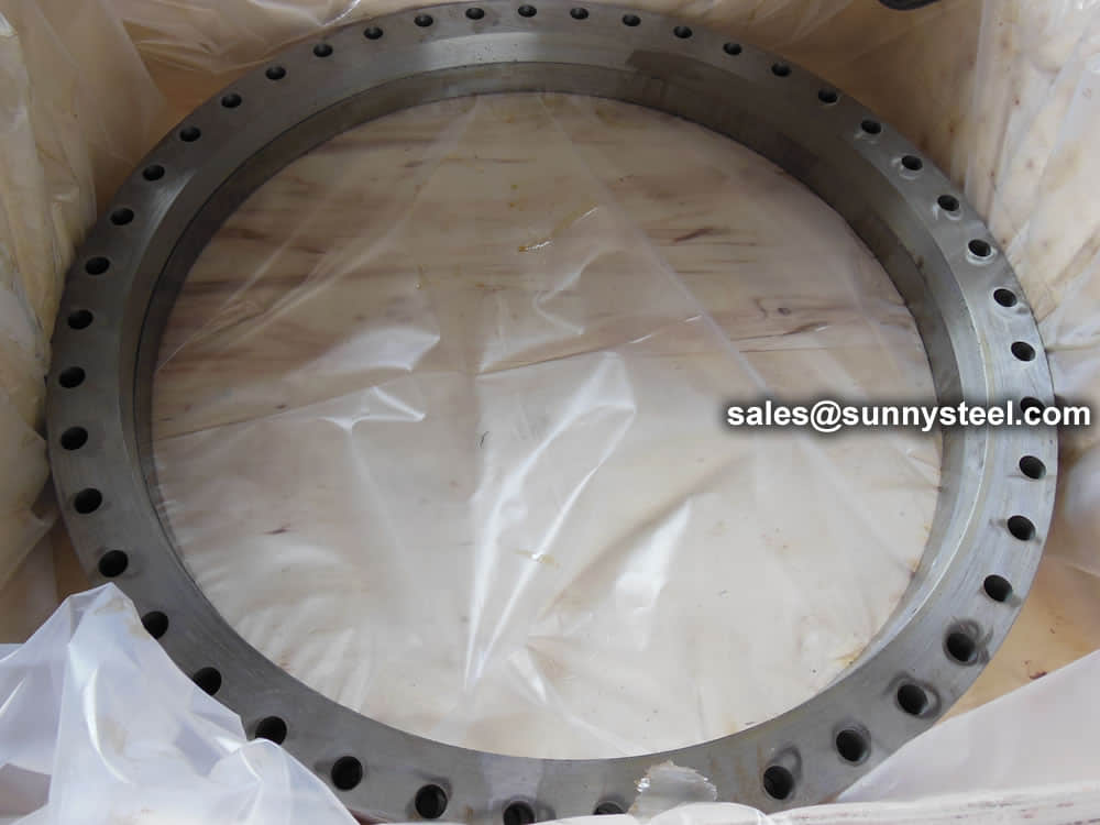
Delivery
Steel flanges must be packed with seaworthy packing method then delivery to customers, usually the packing way include wooden box, wooden pallet, iron & steel cage, iron & steel pallet etc.
Flange Inspection
Before dispatching from manufacture each flange is inspected to ensure quality. During an inspection you have to check the following;
Outer & Inner Diameter of body
Bolt Circle & Bolt hole Diameter
Hub Diameter & thickness of weld end
Length of the Hub
Straightness and alignment of the bolt hole
ASME B16.5 and B16.47 standards cover permissible tolerances for inspection.
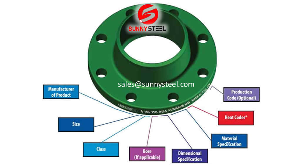
Marking on the flange
Shipping mark stick to outside of package. Following shall be marked on flange body
Manufacturer logo
ASTM material code
Material Grade
Service rating (Pressure-temperature Class))
Size
Thickness (Schedule)
Heat No
Special marking if any QT (Quenched and tempered) or W (Repair by welding)
Packing Because of the normal wooden boxes or wooden pallets have to do fumigation treatment, we usually use plywood pallet or plywood case or box to pack steel flanges without fumigation treatment.
Inquiry
Need to inquire about our products? Fill out the form below and our staff will be in touch!
FAQ
Q: How long is your delivery time?
A: The delivery time of customized products is generally 25 35 days, and non customized products are generally shipped within 24 hours after payment.
Q: Do you provide samples? Is it free?
A: If the value of the sample is low, we will provide it for free, but the freight needs to be paid by the customer. But for some high value samples, we need to charge a fee.
Q: What are your payment terms?
A: T/T 30% as the deposit,The balance payment is paid in full before shipment
Q: What is the packaging and transportation form?
A: Non steaming wooden box and iron frame packaging. Special packaging is available according to customer needs. The transportation is mainly by sea.
Q: What is your minimum order quantity?
A: There is no minimum order quantity requirement. Customized products are tailor made according to the drawings provided by the customer.


 en
en 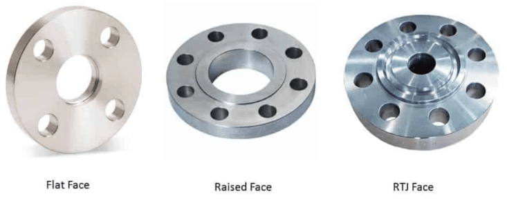


 Tiếng Việt
 Français
 Deutsch
 Русский
 Español
 Italiano
 Svenska
 العربية
 Português
 Bahasa Indonesia
 മലയാളം
 Malagasy
 Afrikaans
 Shqip
Shqip አማርኛ
አማርኛ Հայերեն
 Azərbaycan dili
 Euskara
 Беларуская мова
 বাংলা
বাংলা Bosanski
 Български
 Català
 Cebuano
 Chichewa
 繁體中文
繁體中文 Corsu
Corsu Hrvatski
 Čeština
 Dansk
Dansk Nederlands
 Esperanto
 Eesti
Eesti Filipino
 Suomi
Suomi Frysk
Frysk Galego
 ქართული
 Ελληνικά
 ગુજરાતી
 Kreyol ayisyen
 Harshen Hausa
 Ōlelo Hawaiʻi
 עִבְרִית
 हिन्दी
 Hmong
Hmong Magyar
 Íslenska
 Igbo
Igbo 日本語
日本語 Gaeilge
 Basa Jawa
 ಕನ್ನಡ
ಕನ್ನಡ Қазақ тілі
 ភាសាខ្មែរ
 한국어
한국어 كوردی
كوردی Кыргызча
 ພາສາລາວ
 Latin
Latin Latviešu valoda
 Lietuvių kalba
 Lëtzebuergesch
 Македонски јазик
 Bahasa Melayu
 Maltese
 Te Reo Māori
 मराठी
मराठी Монгол
 ဗမာစာ
ဗမာစာ नेपाली
 Norsk bokmål
 پښتو
پښتو فارسی
فارسی Polski
 ਪੰਜਾਬੀ
 Română
 Samoan
 Gàidhlig
 Српски језик
 Sesotho
 Shona
Shona سنڌي
سنڌي සිංහල
සිංහල Slovenčina
 Slovenščina
 Afsoomaali
 Basa Sunda
 Kiswahili
 Тоҷикӣ
 தமிழ்
தமிழ் తెలుగు
 ไทย
ไทย Türkçe
 Українська
 اردو
اردو O‘zbekcha
 Cymraeg
 isiXhosa
 יידיש
יידיש Yorùbá
 Zulu
Zulu